Modulmerkmale:
• Ausgänge in Halbleitertechnik:
2 Sicherheitsausgänge nach
EN 954-1, 12/96, Kat. 4 oder
4 Sicherheitsausgänge nach
EN 954-1, 12/96, Kat. 3
• konfigurierbar mit PNOZmulti Configurator
• max. 8 Erweiterungsmodule sind an-
schließbar an das Basisgerät PNOZ m1p,
davon dürfen max. 6 Erweiterungsmodule
PNOZ mo1p und PNOZ mo2p sein
• Statusanzeigen
• Querschlussüberwachung zwischen den
Sicherheitsausgängen
• steckbare Klemmen, wahlweise mit
Käfigzugfederanschluss oder
Schraubanschluss
Funktionsbeschreibung
Arbeitsweise:
Die Funktionsweise der Ein- und Ausgänge
des Sicherheitssystems hängt von der mit
dem PNOZmulti Configurator erstellten
Sicherheitsschaltung ab. Die Sicherheits-
schaltung wird mittels Chipkarte in das
Basisgerät PNOZ m1p übertragen. Das
Basisgerät PNOZ m1p hat 2 Micro-
Controller, die sich gegenseitig überwachen.
Sie werten die Eingangskreise des Basis-
geräts und der Erweiterungsmodule aus und
schalten abhängig davon die Ausgänge des
Basisgeräts und der Erweiterungsmodule.
Funktionen:
Die LEDs an Basisgerät und Erweiterungs-
modulen zeigen den Status des Sicherheits-
systems PNOZmulti an.
Info:
In der Online-Hilfe des
PNOZmulti Configurators finden Sie
Beschreibungen über die Betriebsar-
ten und alle Funktionen des Sicher-
heitssystems PNOZmulti sowie
Anschlussbeispiele.
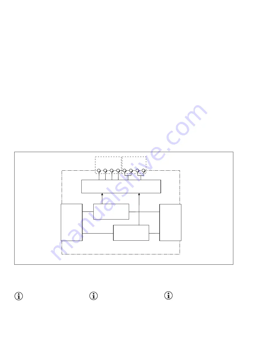
Fig. 1: Innenschaltbild
Fig. 1: Internal wiring diagram
図 1 : 内部配線図
Busanschluss A
Bus connection A
Raccordement du
bus A
Halbleiterausgänge, Versorgungssanschlüsse
Auxiliary outputs, supply connections
Sorties statiques, raccords d'alimentation
Interf
ace
zum v
or
igen Modul
to pre
vious module
av
ec le module
précédent
0 V
24 V
O3
O2
O1
O0
Busanschluss B
Bus connection B
Raccordement du
bus B
Interf
ace
zum nächsten Modul to ne
xt module
av
ec le module
suiv
ant
X1
X2
Module features:
• Outputs use semiconductor technology:
2 safety outputs in accordance with
EN 954-1, 12/96, Cat. 4 or
4 safety outputs in accordance with
EN 954-1, 12/96, Cat. 3
• Can be configured using the PNOZmulti
Configurator
• Max. of 8 expansion modules can be
connected to the PNOZ m1p base unit;
max. of 6 of these may be PNOZ mo1p
and PNOZ mo2p expansion modules
• Status indicators
• Monitors shorts between the safety outputs
• Plug-in terminals, either with cage clamp
connection or screw connection
Function description
Operation:
The function of the inputs and outputs on the
safety system depends on the safety circuit
created using the PNOZmulti Configurator. A
chip card is used to download the safety
circuit to the PNOZ m1p base unit. The
PNOZ m1p base unit has 2 microcontrollers
that monitor each other. They evaluate the
input circuits on the base unit and expansion
modules and switch the outputs on the base
unit and expansion modules accordingly.
Functions:
The LEDs on the base unit and expansion
modules indicate the status of the PNOZmulti
safety system.
Information:
The online help on the
PNOZmulti Configurator contains
descriptions of the operating modes
and all the functions of the PNOZmulti
safety system, plus connection
examples.
製品の特徴
製品の特徴
製品の特徴
製品の特徴
製品の特徴 :
:
:
:
:
・半導体出力
EN 954‑1, 12/96, Cat. 4 対応の安全出
力2点、または
EN 954‑1, 12/96, Cat. 3対応の安全出力
4点
・PNOZmulti Configuratorを使って、コン
フィグレーションが可能
・PNOZ m1p ベースユニットに最大8台、増
設モジュールを接続可能。そのうち、6台
はPNOZ mo1p および PNOZ mo2p, PNOZ
mo4p増設モジュールを使用可能
・状態表示
・安全出力の短絡監視
・プラグイン端子はスプリングまたはネジ
タイプを用意
機能の特徴
機能の特徴
機能の特徴
機能の特徴
機能の特徴
動作
動作
動作
動作
動作 :
:
:
:
:
安全コントローラの入出力機能は、
PNOZmulti Configuratorを使って作られる
安全回路によって決まります。PNOZ m1p
ベースユニットに安全回路をダウンロード
するために、チップカードが使われます。
PNOZ m1p ベースユニットには、互いを監
視するマイクロコントローラが2個付いて
います。マイクロコントローラは、ベース
ユニットと増設モジュールの入力回路を点
検し、その結果によりベースユニットと増
設モジュールの出力が切り替わります。
機能
機能
機能
機能
機能 :
:
:
:
:
ベースユニットと増設モジュールのLEDが
PNOZmulti 安全コントローラの状態を表示
します。
インフォメーション:
インフォメーション:
インフォメーション:
インフォメーション:
インフォメーション: PNOZmulti の
オンラインヘルプにはオペレーティン
グモード、PNOZmulti 安全コント
ローラの全機能や接続例が含まれま
す。
Summary of Contents for PNOZ mo1p
Page 7: ...Notizen Notes Notes...


