- 6 -
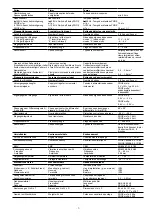
Technische Daten
Elektrische Daten
Versorgungsspannung (U
B
)
über Basisgerät
Spannungstoleranz (U
B
)
Restwelligkeit (U
B
)
Leistungsaufnahme bei U
B
über
Basisgerät
24 V DC
85...120%
± 5%
typ. 1 W
Betrieb
Beim Einschalten der Versorgungs-
spannung am Basisgerät übernimmt das
Sicherheitssystem PNOZmulti die Konfigu-
ration aus der Chipkarte. In der dafür
benötigten Zeit leuchten am Basisgerät die
LEDs "
POWER
", "
DIAG
", "
FAULT
", "
IFAULT
"
und "
OFAULT
", am
PNOZ ms1p/PNOZ
ms2p
die LEDs "
POWER
", "
SHAFT 1/2
",
"
FAULT
", "
X12
" und "
X22
".
Das Sicherheitssystem PNOZmulti ist
betriebsbereit
, wenn am Basisgerät die
LEDs "
POWER
" und "
RUN
", am
PNOZ
ms1p/PNOZ ms2p
die LED "
POWER
"
dauerhaft leuchten.
Das
PNOZ ms1p/PNOZ ms2p
meldet
während des Betriebs
• den Status der Stillstands-, Drehzahl- und
Drehrichtungsüberwachung
• und Fehler
an das Basisgerät.
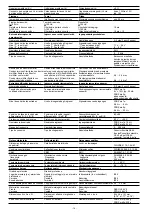
LED-Anzeigen des PNOZ ms1p/PNOZ
ms2p
LED aus
LED leuchtet
LED blinkt
LED blitzt
LED-Zustand/
LED condition/
État de la LED
LED
POWER
FAULT
SHAFT 1
SHAFT 2
X12
X22
I10, I11, I20, I21
Bedeutung
Versorgungsspannung liegt an
externer Fehler, der zum sicheren
Zustand führt; an den
Inkrementalgeber-Eingängen,
deren LEDs blitzen, tritt der Fehler
auf, z. B. Querschluss
interner Fehler, der zum sicheren
Zustand führt
Geber- oder Verdrahtungsfehler
Achse 1 und/oder Achse 2 sind im
Normalbereich (kein Stillstand,
keine Überdrehzahl)
Achse 1 und/oder Achse 2 meldet
Stillstand
Achse 1 und/oder Achse 2 meldet
Überdrehzahl
Inkrementalgeber an Klemmen
X12 und/oder X22 sind korrekt
angeschlossen
Näherungsschalter an Klemme I10,
I11, I20, I21 ist bedämpft
INFO
Die LED an den Klemmen
24V
und
0V
haben keine Funktion.
Fonctionnement
Lors de la mise sous tension de l’appareil de
base, le système de sécurité PNOZmulti
charge la configuration enregistrée sur la
carte à puce. Pendant le temps nécessaire à
cet effet, les LED "
POWER
", "
DIAG
",
"
FAULT
", "
IFAULT
" et "
OFAULT
" de
l’appareil de base, et les LED "
POWER
",
"
SHAFT 1/2
", "
FAULT
", "
X12
" et "
X22
" du
PNOZ ms1p/PNOZ ms2p
s’allument.
Le système de sécurité PNOZmulti est
prêt à fonctionner
lorsque les LED
"
POWER
" et "
RUN
" de l’appareil de base et
la LED "
POWER
" du
PNOZ ms1p/PNOZ
ms2p
restent allumées.
Le module
PNOZ ms1p/PNOZ ms2p
signale
à l’appareil de base, pendant son
fonctionnement
• l’état de surveillance d’arrêt, de vitesse de
rotation et de sens de rotation ainsi que
• les erreurs.
État des LED du PNOZ ms1p/PNOZ ms2p
LED éteinte
LED allumée
LED clignote
LED émet un flash
INFORMATION
Les LED des bornes
24V
et
0V
n’ont
aucune fonction.
Signification
appareil sous tension
erreur externe qui mène à un état
sûr ; l’erreur, p. ex. un court-circuit,
se trouve au niveau des entrées du
codeur incrémental dont les LED
clignotent
erreur interne qui mène à un état
sûr
erreur de raccordement ou de
codeur
axe 1 et/ou axe 2 dans la plage
normale (pas d’arrêt, pas de
survitesse)
axe 1 et/ou axe 2 signale un arrêt
axe 1 et/ou axe 2 signale une
survitesse
les codeurs incrémentaux des
bornes X12 et/ou X22 sont
raccordés correctement
le détecteur de proximité des
bornes I10, I11, I20, I21 est activé
Caractéristiques techniques
Données électriques
Tension d’alimentation (U
B
)
par l’appareil de base
Plage de la tension d’alimentation (U
B
)
Ondulation résiduelle (U
B
)
Consommation pour U
B
sur
l’appareil de base
Fehler - Störungen
Überwachung der Drehrichtung: Tritt ein
interner Fehler auf oder ein Fehler durch einen
defekten Inkrementalgeber (LED "
FAULT
"
leuchtet oder blinkt), kann für ca. 500 ms eine
falsche Drehrichtung gemeldet werden.
Erreurs - Défaillances
Surveillance du sens de rotation : en cas
d’erreur interne ou liée à une défectuosité d’un
codeur incrémental (la LED "
FAULT
" s’allume
ou clignote), un sens de rotation erroné peut
être signalé pendant environ 500 ms.
Operation
When the supply voltage on the base unit is
switched on, the PNOZmulti safety system
copies the configuration from the chip card.
During the time necessary for this process
the following LEDs are illuminated on the
base unit "
POWER
", "
DIAG
", "
FAULT
",
"
IFAULT
" and "
OFAULT
", and on the
PNOZ ms1p/PNOZ ms2p
the LEDs
"
POWER
", "
SHAFT 1/2
", "
FAULT
", "
X12
"
and "
X22
".
The PNOZmulti safety system is
ready
when the "
POWER
" and "
RUN
" LEDs on
the base unit are continuously illuminated,
and on the
PNOZ ms1p/PNOZ ms2p
the
"
POWER
" LED.
During operation the
PNOZ ms1p/PNOZ
ms2p
signals
• the status of the standstill, speed and
direction of rotation monitoring
• and faults
to the base unit.
LEDs on the PNOZ ms1p/PNOZ ms2p
LED off
LED on
LED flashes
LED flashes once
INFORMATION
The LEDs on the
24V
and
0V
terminals
have no function.
Key
Supply voltage is present
External fault leading to a safe
condition; the fault is at the
incremental encoder inputs whose
LEDs flash once, e.g. short
across the contacts
Internal fault leading to safe
condition
Encoder or wiring fault
Axis 1 and/or axis 2 are in the
normal range (no standstill, no
overspeed)
Axis 1 and/or axis 2 signalling
standstill
Axis 1 and/or axis 2 signalling
overspeed
Incremental encoders on
terminals X12 and/or X22 are
connected correctly
Proximity switch on terminal I10,
I11, I20, I21 is energised
Faults - malfunctions
Monitoring the direction of rotation: If an
internal fault occurs or a fault due to a faulty
incremental encoder ("
FAULT
" LED
illuminates or flashes), an incorrect direction
of rotation can be signalled for approx.
500 ms.
Technical details
Electrical data
Supply voltage (U
B
)
via base unit
Voltage tolerance (U
B
)
Residual ripple (U
B
)
Power consumption at U
B
via base
unit

