- 7 -
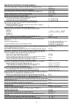
Gehäusematerial/housing material/matériau du boîtier
Gehäuse/Housing/Boîtier
Front/front panel/face avant
Max.Querschnitt des Außenleiters (Schraubklemmen)/Max. cable cross section (screw
terminals)/Capacité de raccordement (borniers à vis)
1 Leiter, flexibel/1 core, flexible/1 conducteur souple
2 Leiter gleichen Querschnitts, flexibel mit Aderendhülse, ohne Kunststoffhülse/
2 core, same cross section flexible with crimp connectors, without insulating sleeve/
2 conducteurs de même diamètre souple avec embout, sans chapeau plastique
ohne Aderendhülse oder mit TWIN-Aderendhülse/without crimp connectors or with TWIN
crimp connectors/souple sans embout ou avec embout TWIN
Anzugsdrehmoment für Schraubklemmen/Torque setting for screw terminals/
couple de serrage (borniers à vis)
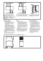
Abmessungen (Schraubklemmen) H x B x T/Dimensions H x W x D (screw terminals)/
Dimensions (borniers à vis) H x P x L
Einbaulage/Fitting Position/Position de montage
Gewicht/Weight/Poids
PPO UL 94 V0
ABS UL 94 V0
0,20 ... 4,0 mm
2
, 24 ... 10 AWG
0,20 ... 2,5 mm
2
, 24 ... 14 AWG
0,20 ... 2,5 mm
2
, 24 ... 14 AWG
0,6 Nm
87 x 45 x 121 mm
beliebig/any/indifférente
375 g
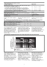
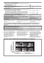
Lebensdauer der Ausgangsrelais/Service Life of Output relays/Durée de vie des relais de sortie
Um ein Versagen der Geräte zu verhindern,
an allen Ausgangskontakten für eine aus-
reichende Funkenlöschung sorgen. Bei
kapazitiven Lasten sind eventuell auftreten-
de Stromspitzen zu beachten. Bei DC-
Schützen Freilaufdioden zur Funken-
löschung einsetzen, um die Lebendauer der
Schütze zu erhöhen.
To prevent failure of the unit, all output
contacts should be fused adequately. With
capacative loads, possible current peaks
are to be avoided. With DC contactors/
relays use suitable spark suppression to
ensure extended life of the contactors/
relays.
Prévoir un dispositif d’extinction d’arc sur
les contacts de sortie pour éviter un
éventuel disfonctionnement du relais.
Tenir compte des pointes d’intensité en cas
de charge capacitive. Equiper les
contacteurs DC de diodes de roue libre .
Anzahl der Kontakte/number of contacts/nombre des contacts
3
2
1
Imax (A) bei Versorgungsspannung DC/with operating
voltage DC/pour tension d’alimentation CC
7,0
8,0
8,0
Imax (A) bei Versorgungsspannung AC/with operating
voltage AC/pour tension d’alimentation AC
6,5
7,5
8,0
Es gelten die 09/01 aktuellen Ausgaben der
Normen
The version of the standards current at 09/
01 shall apply
Se référer à la version des normes en
vigeur au 09/01.
Max. Dauerstrom bei gleichzeitiger Belastung mehrerer Kontakte/Max. continuous current with several contacts
under load simultaneously/Courant permanent max. en cas de charge sur plusieurs contacts (AC1, DC1)
10
1
10
100
1000
10000
0.1
DC13: 24 V
AC15: 230 V
AC1: 230 V
DC1: 24 V
D
Nennbetriebstr
om (A)
GB
Nominal operating current (A)
F
Courant coupé (A)
E
Corriente nominal de ser
vicio (A)
I
Corrente di eser
cizio nominale (A)
NL
Nominale bedrijfsstr
oom (A)
D Schaltspielzahl x 10
3
GB Cycles x 10
3
F
Nombre de manvres x 10
3
E
Número de ciclos x 10
3
I
Numero dei cicli di commutazione x 10
3
NL Aantal schakelingen x 10
3
EG-Konformitätserklärung:
Diese(s) Produkt(e) erfüllen die Anforde-
rungen der Richtlinie 2006/42/EG über
Maschinen des europäischen Parlaments
und des Rates.
Die vollständige EG-Konformitätserklärung
finden Sie im Internet unter www.pilz.com
Bevollmächtigter: Norbert Fröhlich,
Pilz GmbH & Co. KG, Felix-Wankel-Str. 2,
73760 Ostfildern, Deutschland
EC Declaration of Conformity:
This (these) product(s) comply with the
requirements of Directive 2006/42/EC of
the European Parliament and of the Council
on machinery.
The complete EC Declaration of Conformity
is available on the Internet at www.pilz.com
Authorised representative: Norbert
Fröhlich, Pilz GmbH & Co. KG, Felix-
Wankel-Str. 2, 73760 Ostfildern, Germany
Déclaration de conformité CE :
Ce(s) produit(s) satisfait (satisfont) aux
exigences de la directive 2006/42/CE
relative aux machines du Parlement
Européen et du Conseil.
Vous trouverez la déclaration de
conformité CE complète sur notre site
internet www.pilz.com
Représentant : Norbert Fröhlich,
Pilz GmbH & Co. KG, Felix-Wankel-Str. 2,
73760 Ostfildern, Allemagne


