Connecting the Control System PNOZmulti
Installation Manual PNOZmulti Installation Manual
1002265-EN-02
29
Adapters for encoders
Adapters are available for encoders; these adapters record the data between the encoder
and drive and make it available to the motion monitoring module via the RJ45 or Mini-IO fe-
male connector.
Pilz supplies complete adapters as well as ready-made cable with female connectors,
which can be used when making your own adapter. The range of products in this area is
constantly being expanded. Please contact us about the range of adapters that is currently
available.
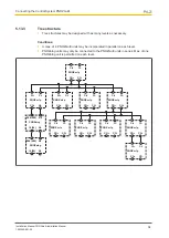
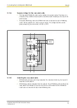
The example below shows a motion monitoring module connected via an adapter.
Encoder
1
8
Mini-IO
Motion Monitoring
Module
5.10
Connection example: analogue input module and speed
monitor
Please note the following guidelines for connecting the shield:
}
Use shielded cable for the input circuit connection cables (6); analogue input circuits
should have twisted pair cables.
}
The supply voltage cables (3) should be physically separate from the input circuit
cables (6).
}
Where the cable enters the control cabinet, the cable shield must be connected to the
earth potential over a wide surface area and with low impedance (connect in star to the
shield bar (5)).
}
Appropriate clamps or shield terminals (7) should be used to fasten the shield braid.
}
The shield bar (5) should be connected with low impedance to PE.
}
The shield bar (5) should be connected with low impedance to the earthing terminal
(10) on the mounting rail.
}
Route the shield as far as the inputs (4), but leave it unconnected.
}
Metallised RJ45 connector housing (8) with connected shield.


