Connecting the Control System PNOZmulti
Installation Manual PNOZmulti Installation Manual
1002265-EN-02
33
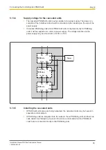
Incorporating PNOZelog units:
}
PNOZelog units may also be included in the series connection. The delay times on the
individual units are also added together with this type of cascading.
}
Remember to consider the switch-on delay and any potential delay time for the outputs
on the PNOZelog units (see operating manual or PNOZelog technical catalogue).
}
When connecting PNOZmulti - PNOZelog, the cascading output “CO-” is not connec-
ted.
CI+
CI-
CO+
A2
S36 (S35)
A2
14
(24)
A2
PNOZ m1p
PNOZelog
Unit 1
Unit 2
CI+
CI-
CO+
A2
PNOZ m1p
Unit 3
S36 (S35)
A2
14
(24)
A2
PNOZelog
Unit 4
5.13.1
System requirements
PNOZmulti Configurator: from Version 3.0.0
Please contact Pilz if you have an older version.
5.13.2
Series connection
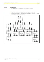
As many PNOZ m1p base units as necessary may be connected in series. The number of
units connected in succession will depend only on the reaction time required by the applica-
tion. As the delay times on the individual units are added together, the reaction time in-
creases with each unit.
CI+
CI-
CO+
CO-
PNOZ m1p
Unit 1
CI+
CI-
CO+
CO-
PNOZ m1p
Unit 2
CI+
CI-
CO+
CO-
PNOZ m1p
Unit x
Delay time on the
PNOZmulti
Switch-off delay
Switch-on delay
Between input and cascad-
ing output
Max. 40 ms
Typ. 100 ms
Between cascading input
and a semiconductor output
Max. 40 ms
Typ. 100 ms
Between cascading input
and a relay output
Max. 60 ms
Typ. 120 ms
Between cascading input
and a cascading output
Max. 40 ms
Typ. 120 ms

