PSEN ma1.3p-20
Operating Manual PSEN ma1.3p-20
22147-EN-05
| 18
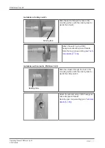
Installation with actuator PSEN ma1.3-12
Attach the bracket using countersunk
screws (M4).
Sensing face
The sensing face at the actuator is marked
by a circle with a bevelled surface in the
shape of the safety switch. The sensing
face can be aligned in 3 directions depend-
ing on the direction of actuation. Slide the
actuator on to the bracket in the required
direction of actuation until the actuator clicks
into place.
The actuator should be secured using a set
screw M3 x 6 mm DIN 319 (supplied with
the device).
Also note the low max. torque setting (see
Adjustment
}
The safety switch may only be used with the corresponding actuator PSEN ma1.3-08 or
PSEN ma1.3-12.
}
Always test the function with a connected evaluation device.
}
The stated operating distances (see
) only apply when the
safety switch and actuator are installed according to the specifications
. Operating distances may deviate if other arrangements are used.
Note the maximum permitted lateral and vertical offset (see
).
Periodic test
}
Carry out a monthly function test on the safety switch and actuator.
}
Always test the function with a connected evaluation device.
}
The safety function may only be checked by qualified personnel.


