background image

Contents

Operating Manual PSEN ma1.3p-20
22147-EN-05

| 3

Introduction 

............................................................................................................................

4

Validity of documentation

..........................................................................................................

4

Using the documentation

..........................................................................................................

4

Definition of symbols

.................................................................................................................

4

Safety 

......................................................................................................................................

5

Intended use

.............................................................................................................................

5

Safety regulations

.....................................................................................................................

5

Safety assessment

...................................................................................................................

5

Use of qualified personnel

........................................................................................................

6

Warranty and liability

................................................................................................................

6

Disposal

....................................................................................................................................

6

For your safety

..........................................................................................................................

6

Unit features 

...........................................................................................................................

7

Function description 

.............................................................................................................

7

Block diagram

...........................................................................................................................

8

Operating distances

..................................................................................................................

8

Lateral and vertical offset

..........................................................................................................

9

Wiring 

......................................................................................................................................

11

Pin assignment

.........................................................................................................................

11

Requirements and connection to evaluation devices 

........................................................

12

Installation 

..............................................................................................................................

15

Adjustment 

.............................................................................................................................

18

Periodic test 

...........................................................................................................................

18

Dimensions in mm 

.................................................................................................................

19

Technical details 

....................................................................................................................

20

Safety characteristic data

.........................................................................................................

22

Order reference 

......................................................................................................................

22

System

......................................................................................................................................

22

Accessories

..............................................................................................................................

22

EC declaration of conformity 

................................................................................................

23

Summary of Contents for PSEN ma1.3p-20

Page 1: ...PSEN ma1 3p 20 Operating Manual 22147 EN 05 PSEN sensor technology...

Page 2: ...nta tion will be gratefully received Source code from third party manufacturers or open source software has been used for some components The relevant licence information is available on the Internet...

Page 3: ...6 Warranty and liability 6 Disposal 6 For your safety 6 Unit features 7 Function description 7 Block diagram 8 Operating distances 8 Lateral and vertical offset 9 Wiring 11 Pin assignment 11 Requirem...

Page 4: ...particularly important is identified as follows DANGER This warning must be heeded It warns of a hazardous situation that poses an immediate threat of serious injury and death and indicates preventive...

Page 5: ...ide the technical details see Technical details 20 NOTICE EMC compliant electrical installation The product is designed for use in an industrial environment The product may cause interference if insta...

Page 6: ...liability will be rendered invalid if The product was used contrary to the purpose for which it is intended Damage can be attributed to not having followed the guidelines in the manual Operating pers...

Page 7: ...tails 20 Design Safety switch with round design Actuator with round design PSEN ma1 3 08 Actuator with square design PSEN ma1 3 12 various directions of actuation pos sible Operation Magnetic Switchin...

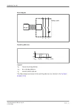
Page 8: ...2 6 3 Actuator Safety switch Magnet Operating distances Sao So Sr Sar mm Somin On Off Legend Sao Assured operating distance Somin Min operating distance Sar Assured release distance The offset indepen...

Page 9: ...vertical offset Actuator PSEN ma1 3 08 2 1 3 Legend 1 Lateral offset 2 Vertical offset 3 Sensing faces Assured operating distance Sao in mm Lateral offset Vertical offset 0 2 4 0 8 0 7 0 5 5 2 7 0 6...

Page 10: ...distance Sao in mm Lateral offset Vertical offset 0 1 2 0 12 0 10 0 8 0 2 12 0 10 0 8 0 4 11 0 9 5 7 5 The stated values are valid at a temperature of 20 C Negative vertical offset not permitted 1 2 3...

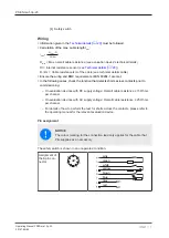
Page 11: ...lowing cases check the function that detects shorts across contacts prior to commissioning On evaluation devices with DC supply voltage Overall cable resistance 15 Ohms per channel On evaluation devic...

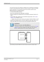
Page 12: ...ice with defined properties Certified Pilz evaluation devices are for example PNOZelog for safety gate monitoring PNOZ e1p PNOZ e1 1p PNOZ e1vp PNOZ e5 11p PNOZ e6vp PNOZ e6 1p PNOZpower for safety ga...

Page 13: ...data of the evaluation device must fulfil the requirements in the Technical details 20 of PSEN ma1 3p 20 Always comply with the max switching current safety contacts of PSEN ma1 3p 20 Outputs at the...

Page 14: ...5 14 Examples for connection to Pilz evaluation devices S21 S22 S11 S12 1 2 3 4 5 6 7 8 PNOZ s3 PSENmag White Green Yellow Pink I0 I1 PNOZmulti PSENmag 3 1 2 4 T1 T0 5 6 7 8 White Green Yellow Pink Le...

Page 15: ...ors must be installed so that the bevelled surface on the safety switch and the bevelled surface of the actuator face each other precisely CAUTION Potential loss of safety function due to changed devi...

Page 16: ...Should be kept away from iron swarf Should not be exposed to strong magnetic fields Prevent the safety switch and actuator being exposed to heavy shock or vibration Make sure that the safety switch a...

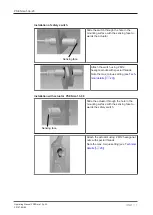
Page 17: ...r Attach the switch using 2 M12 hexagonal nuts with special threads Note the max torque setting see Tech nical details 20 Installation with actuator PSEN ma1 3 08 Sensing face Slide the actuator throu...

Page 18: ...note the low max torque setting see Technical details 20 Adjustment The safety switch may only be used with the corresponding actuator PSEN ma1 3 08 or PSEN ma1 3 12 Always test the function with a c...

Page 19: ...1 3p 20 22147 EN 05 19 Dimensions in mm Safety switch 200 10 26 8 12 5 2 42 6 2 59 1 33 9 Actuator PSEN ma1 3 08 M12x1 11 2 21 25 2 Actuator PSEN ma1 3 12 20 10 M12 20 20 10 M3 20 5 24 1 10 7 5 9 6 2...

Page 20: ...Lowest operating current Im 1 mA 1 mA Switching voltage 24 V 24 V Internal resistance 10 Ohm 10 Ohm Max switching current safety con tacts 0 2 A 0 2 A Max breaking capacity safety con tacts 5 W 5 W M...

Page 21: ...lease distance Sr 12 mm 16 mm Repetition accuracy switching distances 5 5 Min distance between safety switches 25 mm 35 mm Sensor flush installation in accord ance with EN 60947 5 2 Yes follow install...

Page 22: ...226 PSEN ma1 3p 20 PSEN ma1 3 12 12mm 1unit Magnetic safety switch actu ator cube with assured oper ating distance 12 mm 8 pin M8 male connector 506 236 PSEN ma1 3p 20 1switch Magnetic safety switch...

Page 23: ...aight 533 156 PSEN cable M8 8sf M8 8sm 2m 2 m M 8 8 pin male connector straight M 8 8 pin fe male con nector straight 533 157 Adapter PSEN converter M8 8sf M12 8sm 0 25 m M12 8 pin male con nector str...

Page 24: ...yNET p THE SPIRIT OF SAFETY are registered and protected trademarks of Pilz GmbH Co KG in some countries We would point out that product features may vary from the details stated in this document depe...

Reviews: