PSEN ma1.3p-20
Operating Manual PSEN ma1.3p-20
22147-EN-05
| 11
[4] Safety switch
Wiring
}
Information given in the
}
Calculation of the max. cable length l
max
:
R
lmax
- R
i
R
l
/ km
I
max
=
R
lmax
= Max. overall cable resistance (see evaluation device's technical details)
Ri = Internal resistance sensor (see
)
R
l
/ km = Cable resistance/km of the cable (see technical details cable)
}
Ensure the wiring and EMC requirements of EN 60204-1 are met.
}
In the following cases, check the function that detects shorts across contacts prior to
commissioning:
– On evaluation devices with DC supply voltage: Overall cable resistance ≥ 15 Ohms
per channel
– On evaluation devices with AC supply voltage: Overall cable resistance ≥ 25 Ohms
per channel
– For details of how to perform the test for shorts across the contacts, please refer to
the operating manual for the relevant evaluation device.
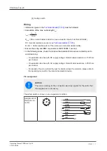
Pin assignment
NOTICE
The colour marking for the connection lead only applies for the cable that
Pilz supplies as an accessory
The safety switch is shown in an unoperated condition.
Assignment of
the 8-pin con-
nector
pink
green
white
yellow
brown
blue
red
grey
NC
NC


