Project configuration
Operating Manual PSEN op2B/1 Series
1003357-EN-02
30
[3]
[4]
[5]
[6]
[9]
[7]
[3]
[1]
[2]
[8]
[9]
[9]
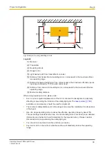
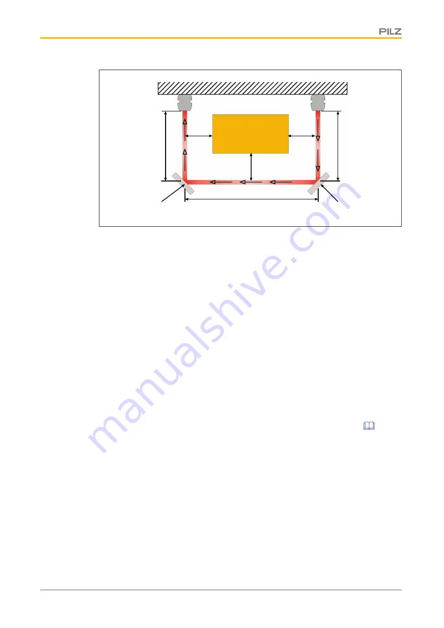
Fig.: Example for using deviating mirrors
Legende
[1] Receiver
[2] Transmitter
[3] Deviating mirrors
[4] Danger zone
[5] Light beams' path from transmitter to receiver
[6] Distance from transmitter to deviating mirror, corresponds to the maximum effect-
ive operating range
[7] Distance between deviating mirrors, corresponds to the maximum effective operat-
ing range, reduced by 15% for each mirror used
[8] Distance from receiver to deviating mirror, corresponds to the maximum effective
operating range
[9] Minimum safety distance
When using deviating mirrors, please note:
}
Even a minor angular displacement of the mirror can lead to misalignment, adversely
affecting or preventing the function of the
safety light grid. The
laser pointer [
60]
available as an accessory should be used for alignment.
}
The minimum safety distance [7] to the danger zone must be maintained for all sections
of the beam.
}
Use of a single deviating mirror reduces the effective operating range by about 15%.
This percentage increases when two or more deviating mirrors are used (more detailed
information is provided in the technical data for the relevant mirror). Please consider
this reduction when positioning the safety light grid.
}
You should not use more than three mirrors per device.
}
Any dust or dirt on the mirror’s reflective surface will drastically reduce the operating
range.

