background image

Commissioning

Operating Manual PSEN op2B/1 Series
1003357-EN-02

44

1

2

3

4

5

6

7

8

ON

Fig.: DIP switches 4 and 8 in OFF position = With restart interlock

7.2

Orientation

7.2.1

General guidelines

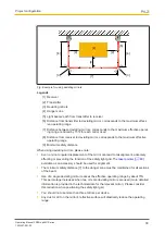
For the safety light grid to function properly,


the transmitter and receiver must be aligned.

Optimum alignment is achieved when the optical axes of the first and last beam from the
transmitter coincide with the optical axes of the corresponding elements on the receiver.
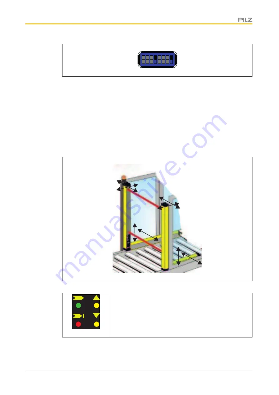
The positions of the transmitter and receiver on the safety light grid,


and the muting sensors

if present, can be modified in accordance with the following diagram.

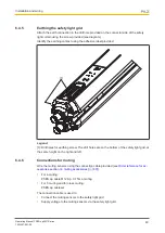
The yellow LEDs High Align [3] and Low Align [4] indicate the status of the alignment.

[1]

[2]

[3]

[4]

}

If the alignment for the upper beam is correct, the LED High
Align [3] will light

}

If the alignment for the lower beam is correct, the LED Low
Align [4] will light

}

If both beams are aligned correctly and the LEDs are lit, the
green LED will also light [1]

The alignment of a type without muting set is described under Safety light grid alignment.

Summary of Contents for PSEN op2B-2-050/1

Page 1: ...PSEN op2B 1 Series Operating Manual 1003357 EN 02 PSEN sensor technology...

Page 2: ...KG Copies may be made for internal purposes Suggestions and comments for improving this documentation will be gratefully received Pilz PIT PMI PNOZ Primo PSEN PSS PVIS SafetyBUS p SafetyEYE SafetyNET...

Page 3: ...on description 13 4 1 Basic function 13 4 1 1 Function settings when delivered 14 4 2 Restart after unit is triggered 14 4 3 Reset function 15 4 4 EDM 16 4 5 Muting 17 4 5 1 Technical implementation 1...

Page 4: ...elines 44 7 2 2 Safety light grid alignment 45 7 2 3 Muting sensor alignment 46 7 2 4 LED support during alignment 47 7 3 Checking the safety light grid 47 7 4 System connection 48 Section 8 Operation...

Page 5: ...Content Operating Manual PSEN op2B 1 Series 1003357 EN 02 5 Section 13 Attachment 62 13 1 Check list 62...

Page 6: ...on that is particularly important is identified as follows DANGER This warning must be heeded It warns of a hazardous situation that poses an immediate threat of serious injury and death and indicates...

Page 7: ...Introduction Operating Manual PSEN op2B 1 Series 1003357 EN 02 7 INFORMATION This gives advice on applications and provides information on special fea tures...

Page 8: ...rom the transmitter to the receiver The minimum width of the protected field corresponds to the minimum operating range stated in the Technical details 56 2 2 Unit features Safety light grids in the P...

Page 9: ...tion on muting accessories 60 1 2 3 4 5 6 7 Fig View of safety light grid without integrated muting sensors Legende 1 Receiver 2 Transmitter 3 LED on receiver transmitter 4 Height of the protected fie...

Page 10: ...PSEN op muting bracket kit Mounting bracket for one muting sensor PSEN op cableset Connection cable for T muting 4 core shielded 2 4 Scope Safety light grid with body resolution without integrated mu...

Page 11: ...l environment Interference may occur if used within a domestic environment Before using the safety light grid check whether the safety light grid s housing material can withstand the chemical substanc...

Page 12: ...standards and guidelines for safety technology It is the company s responsibility only to employ personnel who Are familiar with the basic regulations concerning health and safety accident preven tio...

Page 13: ...are set via DIP switches which are located beneath a flap on the connector side of the safety light grid The electrical connection is made via an M12 connector which is positioned underneath the prof...

Page 14: ...triggered If the safety light grid has switched off the OSSDs the connected machine is stopped Once the protected field is clear again the safety light grid must be reset to its normal oper ating stat...

Page 15: ...will be used is set during commissioning via DIP switches 4 and 8 see Setting the functions 42 4 3 Reset function In the event of an internal error on the safety light grid the safety light grid switc...

Page 16: ...ce Monitoring EDM also known as feedback loop monitoring EDM only needs to be activated if the contactors are controlled directly A test is performed to see that the N C contacts switch if the state o...

Page 17: ...see Setting the functions 42 4 5 Muting If the safety light grid is equipped with separate muting sensors the muting function can be used to overwrite the safety light grid during operation subject t...

Page 18: ...scription Operating Manual PSEN op2B 1 Series 1003357 EN 02 18 A1 B1 A1 B1 Fig Muting in one direction Expansion with L muting set A1 B1 A1 B1 A2 B2 A2 B2 Fig Muting in two directions Expansion with T...

Page 19: ...onveyor speeds that are intended to arise during operation Different conveyor speeds in the area of the safety light grid should be prevented 4 5 1 Technical implementation The safety light grid has t...

Page 20: ...ng status Use a mechanical barrier see diagram to prevent access to the danger zone once muting is ended Fig Application for muting in one direction Danger zone is safeguarded once muting is ended The...

Page 21: ...On Off On Off tAB Fig Timing diagram for L type muting Legend tAB Time from the activation of the first sensor to the activation of the second sensor max 4 s tMoff Once this time has elapsed the mutin...

Page 22: ...status Material on the conveyor passes the safety light grid and the first muting sensor on the output side muting lamp flashes sig nalling the muting status Material has left the area of the first m...

Page 23: ...rror in the operating cycle For example if there is a pallet in the protected field and the conveyor can no longer be switched on because the safety light grid is keeping the OSSD switched off because...

Page 24: ...right flashes yellow 1 2 3 4 Automatic ending of override function The override function is ended automatically when one of the following conditions is met Muting timeout has elapsed The conditions ne...

Page 25: ...essing the data from muting sensors and can be upgraded to L or T types using the muting sensors available as accessories Use the following item numbers for the upgrade PSEN op2 1 L Muting Set L mutin...

Page 26: ...12 is S K t1 t2 C s Minimum distance in mm measured from the start of the protected field to the danger source K Approach speed at which the object body to be detected is nearing the danger zone in mm...

Page 27: ...ce from safety light grid to reflective surface Opening angle of the light beams emitted by the safety light grid The receiver would detect the reflection from the reflective surface as a secondary be...

Page 28: ...stalled steps must be taken to ensure that the transmitter on one safety light grid does not interfere with the receiver on another safety light grid A layout as shown in the diagram below can cause p...

Page 29: ...safety light grids Legend 1 Opaque surface 5 5 Use of deviating mirrors Danger zones with different but adjacent access sides can be monitored using a safety light grid in conjunction with well positi...

Page 30: ...using deviating mirrors please note Even a minor angular displacement of the mirror can lead to misalignment adversely affecting or preventing the function of the safety light grid The laser pointer 6...

Page 31: ...e type of the relevant muting sensor see Technical details of the muting sensor Prevent access to the danger zone during muting The muting sensors must detect material and allow it to pass must detect...

Page 32: ...he application example 4 muting sensors Muting in two directions L A1 B1 1 A2 B2 DA B V DMutingOff DA B Fig Distances between muting sensors 4 muting sensors Legende 1 Safety light grid A1 First mutin...

Page 33: ...n muting sensor A1 and the position from which the muting function is turned off again when con sidering the transport direction from A1 to A2 Distances for muting with 4 sensors Muting in one directi...

Page 34: ...iagram By arranging the muting sensors asymmetrically you ensure that the muting sensors must activate consecutively in order to activate a muting state see diagram A1 1 B2 V d2 Fig Distances between...

Page 35: ...oves on both units 2 Place a mounting bracket on the pins and secure the bracket with the pins 3 Use screws to provisionally fix the mounting bracket to the mounting surface 4 Align the safety light g...

Page 36: ...ting profile for attaching the muting sensor 2 Safety light grid on mounting surface Fix the muting sensor with the small plates to the mounting profile 1 2 1 1 Hexagonal screws for attaching the moun...

Page 37: ...y light grid is already equipped with internal filter capacitors We would advise against using additional external components Use the connection cable available as an accessory to wire the safety ligh...

Page 38: ...ng sensor input 1 Green 4 EDM N C contact for feedback loop monitoring to ensure that downstream consumers are dis connected Yellow 5 OSSD1 Pulsed safety output 1 Grey 6 OSSD2 Pulsed safety output 2 P...

Page 39: ...ight grid PIN Designation Description Cable colour 1 24 VDC Supply voltage for external muting sensor Brown 2 n c White 3 0 VDC Supply voltage for external muting sensor Blue 4 n c Black 5 n c Grey n...

Page 40: ...ll holes for earthing screw The drill holes are on the bottom of the safety light grid at the same height on the right and left 6 4 6 Connections for muting Wire the muting sensors using the connectio...

Page 41: ...light grid 2 4 Muting A1 Muting B2 Fig Wiring of 2 muting sensors for cross muting on the receiver s 5 pin connector Earthing of muting sensors Attach the earth connection in the drill hole provided...

Page 42: ...angle to the safety light grid see diagram 2 Gently press the tip of the screwdriver downwards and lever the cover open 7 1 2 Activate muting Muting only needs to be activated in the case of L muting...

Page 43: ...the specifications of EN ISO 61496 1 Avoid a situation in which sustained muting is not detected Procedure for setting to Set DIP switches 1 and 5 to OFF 7 1 4 Activate EDM EDM only needs to be activa...

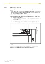
Page 44: ...responding elements on the receiver The positions of the transmitter and receiver on the safety light grid and the muting sensors if present can be modified in accordance with the following diagram Th...

Page 45: ...yone from accessing the protected field during the whole time that alignment takes place 5 Check that the lower green LED and the yellow LED on the transmitter are lit The transmitter is ready for ope...

Page 46: ...ver must light 2 Use the LED to check the alignment of the muting sensors 3 Modify the position of the muting sensors on the safety light grid until the red LEDs on the sensors go out see diagram Vert...

Page 47: ...the safety light grid including any existing muting sensors are aligned and attached correctly The red LED should not light up if gentle pressure is applied to the edges of the safety light grid Check...

Page 48: ...he monitored machine must be shut down 7 4 System connection This section provides information on how to connect the safety light grid to an evaluation device A safety relay from the PNOZsigma series...

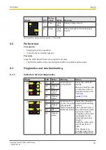
Page 49: ...en detected OSSDs are in an OFF state 3 Restart Align Lights red Irrelevant during normal operation In operating mode with restart in terlock Object has been detected safety light grid is in a safe co...

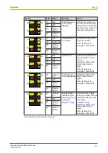
Page 50: ...ooting 8 3 1 Indicators for fault diagnostics Display LED Status Meaning Action 1 2 3 4 1 Off Functional error on the OSSD Check the connected OSSDs Make sure that the load corresponds to the in forma...

Page 51: ...the alignment of the transmitter to the re ceiver Switch the safety light grid off and then on again If the display is un changed contact Pilz 2 Off 3 Off 4 Flashes yellow 1 2 3 4 1 Flashes red Functi...

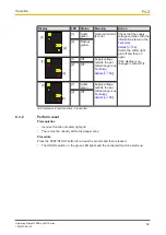
Page 52: ...t Pilz 2 Flashes yellow 1 2 1 Off Supply voltage outside the per mitted range see Technical details 56 2 Off 1 2 1 Lights green Supply voltage outside the per mitted range see Technical details 56 2 O...

Page 53: ...light unit must change from green to red and the movement causing the hazard must be switched off 9 1 3 Check after plant machine modification Check the safety light grid each time the plant machine i...

Page 54: ...PSEN op2B 1 Series 1003357 EN 02 54 Moist cotton cloths should be used for cleaning Avoid using Alcohol Solvents Cloths made of wool Cloths made of synthetic material The lens covers should be cleaned...

Page 55: ...5 10 Dimensions Safety light grid without integrated muting sensors M12x1 11 18 1 18 41 35 111 40 2 3 Fig Receiver M12x1 11 18 1 18 41 35 111 40 2 3 Fig Transmitter Legende 1 Height of protected field...

Page 56: ...utputs 630804 630805 OSSD safety outputs 2 2 Switching current per output 500 mA 500 mA Times 630804 630805 Response time t1 14 ms 14 ms Environmental data 630804 630805 Ambient temperature Temperatur...

Page 57: ...nce Clmax 65 nF 65 nF Optical data 630806 630807 Opening angle 5 5 deg 5 5 deg Used wavelength range 880 nm 880 nm Semiconductor outputs 630806 630807 OSSD safety outputs 2 2 Switching current per out...

Page 58: ...afety related characteristic data in order to achieve the required safety level for your plant machine Operating mode EN ISO 13849 1 2008 PL EN ISO 13849 1 2008 Category EN 62061 SIL CL EN 62061 PFHD...

Page 59: ...90 1 Protective column for safety light grid H 900 mm 630 951 PSEN op Protective Column 120 1 Protective column for safety light grid H 1200 mm 630 952 PSEN op Protective Column 165 1 Protective colum...

Page 60: ...5 pole 30m Connection cable for light beam devices 5 pole un shielded 30 m 630 297 PSEN op cable axial M12 5 pole 50m Connection cable for light beam devices 5 pole un shielded 50 m 630 364 PSEN op ca...

Page 61: ...retrofit 630 820 PSEN op2 2 T Muting Set T muting sensors to retrofit 630 821 PSEN op muting bracket kit Mounting bracket for one muting sensor 630 824 PSEN op cable M12 4 p 0 75m L muting Connection...

Page 62: ...ds Does the category of the safety light grid match the category required for the plant machine Have the standards applicable for the plant machine been considered 2 Environmental conditions for check...

Page 63: ...ce positioned correctly Is the control device installed and wired cor rectly 8 Check the effectiveness of the safety light grid during the hazardous move ment Is the safety light grid effective throug...

Page 64: ...7 EN 02 64 No Action OK NOT OK Notes 12 Check guard function for protected field of the safety light grid Violate the protected field at various points The hazardous movement must be shut down Check t...

Page 65: ...p ThE SPIrIT Of SAfETY are registered and protected trademarks of Pilz Gmbh Co KG in some countries We would point out that product features may vary from the details stated in this document dependin...

Reviews: