Installation Manual: PSS 3032
2-3
~
=
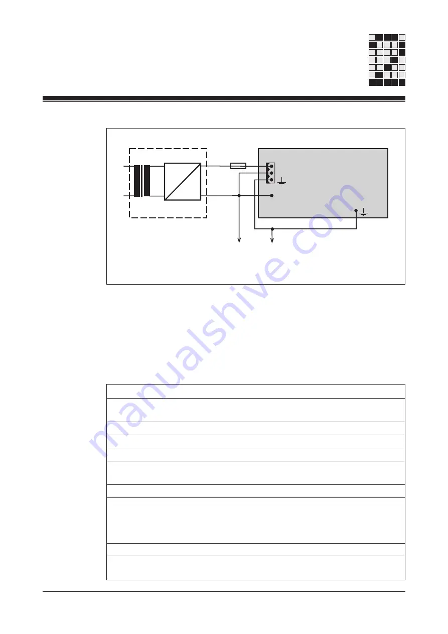
PSS 3032
L1
N
+24 V
0 V
External power supply
24 V
0 V
Functional
earth
Connect in star to the central
earth point
0 V
Connect to the 0 V mains
and earth at a single point
Supply terminal
on the inputs
Supply terminals on the
power supply
Installation
• The system should be installed in an enclosure (e.g. control cabinet)
which conforms to the protection class required.
• When installing the unit in an enclosure such as a control cabinet, the
technical specifications below must be taken into account:
Protection type (EN 60 529, 10/91)
IP 20
Protection class (DIN VDE 0106,
Part 1/A1, 04/90)
1
Mounting position
Vertical
Ambient temperature (DIN IEC 68-2-14, 06/87)
0 ... 60 °C
Storage temperature (EN 60 068-2-1/-2, 03/93) -25 ... +70 °C
Relative humidity
(DIN IEC 68-2-30, 09/86)
Max. 95 % r.h.
Condensation
Not permitted
Vibration (EN 60 068-2-6, 04/95)
Frequency range:
10 ... 100 Hz
Amplitude:
0.1 mm, max. 5g
Shock (DIN IEC 68-2-29)
30g, 11 ms/10g, 16 ms
EMC
EN 50 082-2, 03/95
EN 55 011 A, 08/96
Fig. 2-1: Supplying the system
Summary of Contents for PSS 3032
Page 2: ...Programmable control systems PSS PSS 3032 Installation Manual Item No 19 891...
Page 7: ...Introduction 1 2 Installation Manual PSS 3032 Notes...
Page 24: ...Installation Manual PSS 3032 5 3 Notes...
Page 39: ...Connecting the Inputs and Outputs 5 18 Installation Manual PSS 3032 Notes...
Page 41: ...Interfaces 6 2 Installation Manual PSS 3032 Notes...
Page 43: ...Appendix 7 2 Installation Manual PSS 3032 Notes...


