Installation Manual: PSS 3032
5-15
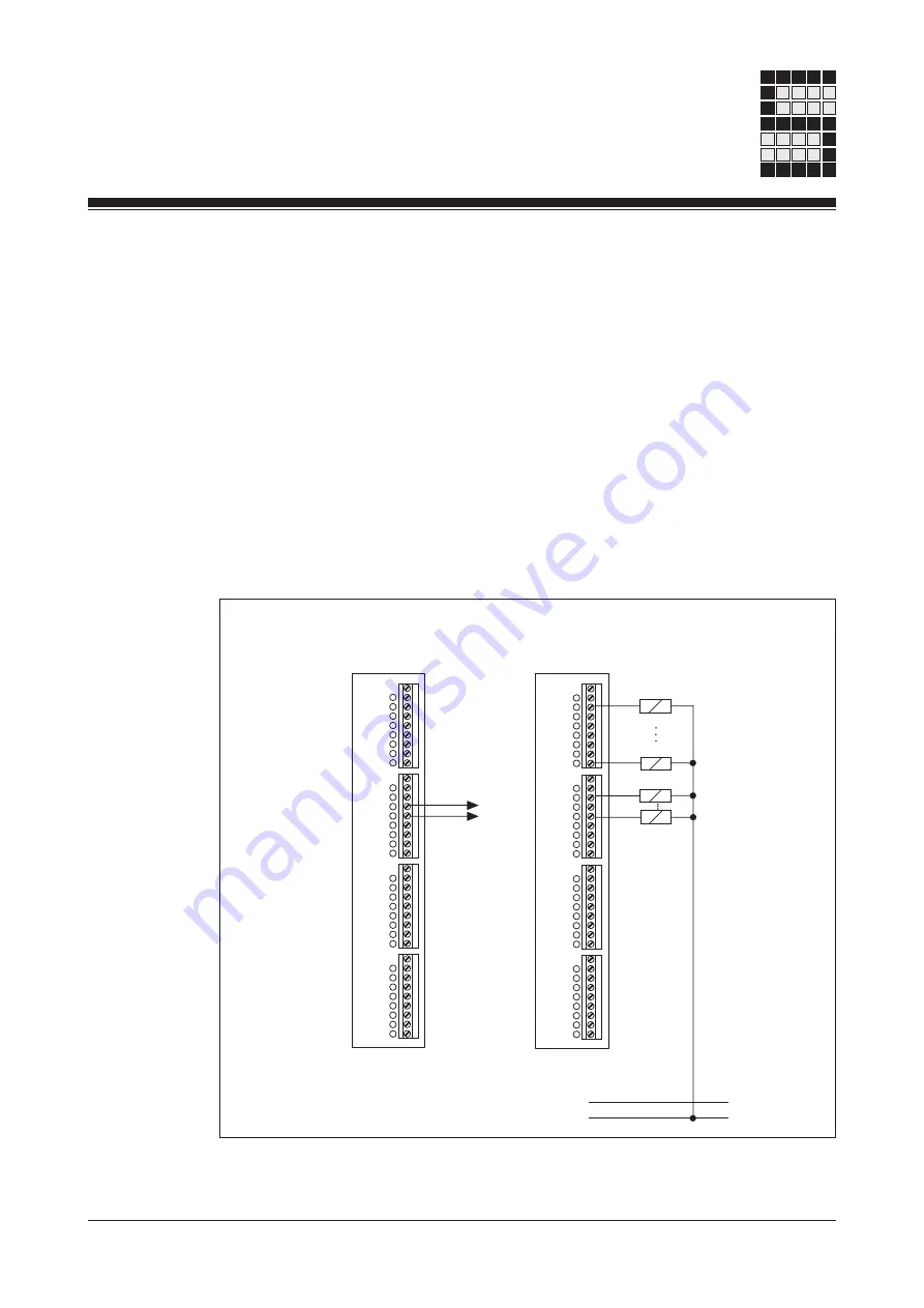
To achieve category 4, dual actuators must be connected to two diffe-
rent outputs.
• If a short circuit occurs between the lead from the output to the load and
the 24 VDC supply lead, it will no longer be possible to switch off the
load. The following remedies are possible:
- Eliminate the possibility of an error by using separate multicore cable
for the 24 VDC
- Use dual actuators for safety
- Use an additional shutdown device such as a main contactor.
Configuration
O -1.16
O +1.16
O 1.8
O 1.9
O 1.10
O 1.11
O 1.12
O 1.13
O 1.14
O -1.17
O +1.17
O 1.15
O/T 1.0
O/T 1.1
I 0.0
I 0.1
I 0.2
I 0.3
0 V
I 0.4
I 0.5
I 0.6
I 0.7
I 0.8
I 0.9
I 0.10
I 0.11
0 V
I 0.12
I 0.13
I 0.14
I 0.15
I 0.16
I 0.17
I 0.18
I 0.19
O -1.16
O +1.16
O 1.8
O 1.9
O 1.10
O 1.11
O 1.12
O 1.13
O 1.14
O -1.17
O +1.17
O 1.15
O/T 1.0
O/T 1.1
I 0.0
I 0.1
I 0.2
I 0.3
0 V
I 0.4
I 0.5
I 0.6
I 0.7
I 0.8
I 0.9
I 0.10
I 0.11
0 V
I 0.12
I 0.13
I 0.14
I 0.15
I 0.16
I 0.17
I 0.18
I 0.19
24 V DC
L+
L-
Please ensure safety regulations and EMC guidelines are observed!
or operate as single-pole
0.5 A outputs
Pulsed outputs supply test
pulses for input devices
T 0
T 1
Summary of Contents for PSS 3032
Page 2: ...Programmable control systems PSS PSS 3032 Installation Manual Item No 19 891...
Page 7: ...Introduction 1 2 Installation Manual PSS 3032 Notes...
Page 24: ...Installation Manual PSS 3032 5 3 Notes...
Page 39: ...Connecting the Inputs and Outputs 5 18 Installation Manual PSS 3032 Notes...
Page 41: ...Interfaces 6 2 Installation Manual PSS 3032 Notes...
Page 43: ...Appendix 7 2 Installation Manual PSS 3032 Notes...


