- 5 -
Gewährleistung und Haftung
SafetyBUS p für IP20
Die Verbindung zu SafetyBUS p (IP20) wird
über einen 9-poligen Sub-D-Stiftstecker
hergestellt.
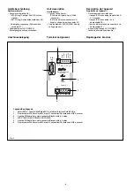
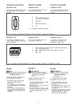
1:
n.c.
2:
CAN_L (brown/brown/marron)
3:
CAN_GND (white/white/blanc)
4:
n.c.
5:
CAN_SHLD
6:
n.c.
7:
CAN_H (grün/green/vert)
8:
n.c.
9:
n.c.
n.c. = nicht belegt/not connected/non affecté
1
9
5
6
SafetyBUS p für IP67
Die Verbindung zu SafetyBUS p (IP67)
wird über einen 5-poligen Schraubsteckverb-
inder (X4) hergestellt.
Fig. 3: X2: 9-poliger Sub-D-Stiftstecker/X2: Male 9-pin D-Sub connector/X2: 9-poliger Sub-D-Stiftstecker
Montage
INFO
Beachten Sie das Kapitel "Installation
und Montage" der "SafetyBUS p
Installationsrichtlinien".
Die PSS SB PASSIVE JUNCTION ist auf
eine Normschiene aufschnappbar.
• Bauen Sie das Gerät in einen Schalt-
schrank mit einer Schutzart von
min. IP54 ein.
• Zur Befestigung auf einer Normschiene
dient ein Rastelement auf der Rückseite
des Geräts.
• Sichern Sie das Gerät bei Montage auf
einer senkrechten Tragschiene durch ein
Halteelement wie z. B. Endhalter oder
Endwinkel.
1 2 3 4
X4
5
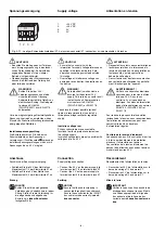
1:
Schirm/shield/Schirm (alternativer Anschluss/alternative connection/xxx)
2:
CAN_L (braun/brown/marron)
3:
GND
(weiß/white/blanc) (CAN_GND und/and/et VCC_GND)
4:
GND
(0V)
5:
GND
(0V)
Fig. 4: X4: 5-poliger Schraubsteckverbinder/X4: 5-pin screw connector/X4 : connecteur à vis débrochable à 5 broches
Warranty and liability
SafetyBUS p for IP20
Connection to SafetyBUS p (IP20) is via a
male 9-pin D-Sub connector.
SafetyBUS p for IP67
Connection to SafetyBUS p (IP67) is via
a 5-pin screw connector (X4).
Installation
INFORMATION
Please refer also to the chapter
entitled "Installation and Assembly" in
the "SafetyBUS p Installation
Manual".
The PSS SB PASSIVE JUNCTION is
suitable for DIN rail mounting.
• The device should be installed in a control
cabinet with a protection type
of at least IP54.
• There is a notch on the back of the unit for
DIN rail attachment.
• If you are installing the unit on to a vertical
DIN rail, ensure that it is mounted securely
by using a retaining bracket or an end
angle.
Garantie et responsabilité
SafetyBUS p pour IP20
La connexion au SafetyBUS p (IP20) est
établie via un connecteur mâle Sub-D à
9 broches.
SafetyBUS p pour IP67
La connexion au SafetyBUS p (IP67)
est établie via un connecteur à vis
débrochable à 5 broches (X4).
Montage
INFORMATION
Veuillez tenir compte du chapitre
« Installation et montage » des «
Directives d’installation du
SafetyBUS p ».
Le PSS SB PASSIVE JUNCTION est
encliquetable sur un rail normalisé.
• Installer l’appareil dans une armoire
possédant un indice de protection
d’au moins IP54.
• Un élément de fixation sur la face arrière
de l’appareil permet une installation sur un
rail normalisé.
• Immobiliser l’appareil monté sur un profilé
support vertical à l’aide d’un élément de
maintien, par exemple : un support
terminal ou une équerre terminale.

