- 7 -
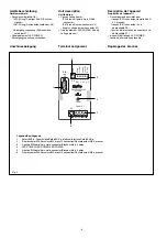
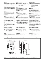
96 (3.77")
48 (1.88")
72 (2.83)
IP67 Line X4
Shield
IP20
Line
X2
Shield
br-LO
W
wt-GND gn-HIGH
rd-VCC
Power X1
Power
X0
1
2
3
4
1 2 3 4 5
X3
Passive Junction
311059
0V
24V
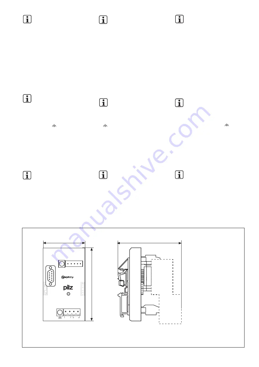
Fig. 6: Abmessungen mit SafetyBUS p-Stecker/Dimensions with SafetyBUS p connector/Abmessungen mit SafetyBUS p-Stecker
INFO
Beachten Sie die Angaben im Kapitel
"Installation und Montage" der
"SafetyBUS p Installationsrichtlinien".
IP20-Strang
Verbinden Sie den Kabelschirm
einmal
für
den gesamten Hauptstrang impedanzarm mit
der Schirmschiene oder Erdungsschiene
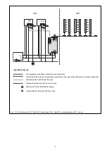
(Fig 1).
IP67-Strang
• Führen Sie
den Kabelschirm des IP67-
Strangs auf einen der Anschlüsse der
beiden Klemmleisten X4 (SHIELD) oder
X3 (SHIELD).
INFO
Empfehlung: Legen Sie den Kabel-
schirm des IP67-Strangs an der
Klemme X3 (SHIELD) (siehe Fig. 2)
an.
• Verbinden Sie die Anschlüsse der
Klemmleiste X0 (
) impedanzarm mit der
Schirmschiene oder Erdungsschiene (Fig.
1).
• Beachten Sie die Angaben der Richtlinie
"SafetyBUS p - IP67 Physical Layer
Concept" des SafetyBUS p Club Interna-
tional e.V.
Gerät in Betrieb nehmen
INFO
Beachten Sie das Kapitel "Inbetrieb-
nahme" der "SafetyBUS p
Installationsrichtlinien".
Betrieb
Das Gerät ist
betriebsbereit
, wenn die LED
"POWER" dauerhaft leuchtet.
Abmessungen in mm (")
INFORMATION
Please refer to the information in the
chapter entitled "Installation and
Assembly" in the "SafetyBUS p
Installation Manual".
IP20 branch
Connect the shielded screening with low
impedance to the screen bar or earth bar;
this only needs to be done
once
for the
whole main branch (Fig 1).
IP67 branch
• Connect
the cable shield of the IP67
branch to one of the connections on the
two terminal blocks X4 (SHIELD) or X3
(SHIELD).
INFORMATION
Recommendation: Connect the cable
shield of the IP67 branch to terminal
X3 (SHIELD) (see Fig. 2).
• Connect the X0 terminal block connections
( ) with low impedance to the screen bar
or earth bar (Fig. 1).
• Follow the guidelines in the "SafetyBUS p -
IP67 Physical Layer Concept" published
by the SafetyBUS p Club International e.V.
Commissioning the unit
INFORMATION
Please refer also to the chapter
entitled "Commissioning" in the
"SafetyBUS p Installation Manual".
Operation
The unit is
ready for operation
when the
"POWER" LED is lit continuously.
Dimensions in mm (")
INFORMATION
Veuillez tenir compte des indications
mentionnées dans le chapitre
« Installation et montage » des
« Directives d’installation du
SafetyBUS p ».
Tronçon IP20
Relier avec une faible impédance et
une
seule fois
le câble de blindage, pour
l’ensemble du tronçon principal, au rail de
blindage ou au rail de mise à la terre (fig. 1).
Tronçon IP67
• Amener
le câble de blindage du tronçon
IP67 sur l’un des raccordements des deux
borniers X4 (SHIELD) ou X3 (SHIELD).
INFORMATION
Recommandation : appliquer le câble
de blindage du tronçon IP67 sur la
borne X3 (SHIELD) (cf. fig. 2).
• Relier, avec une faible impédance, les
raccordements du bornier X0 ( ) au rail
de blindage ou au rail de mise à la terre
(fig. 1).
• Respecter les indications mentionnées
dans les directives « SafetyBUS p - IP67
Physical Layer Concept » du SafetyBUS p
Club International e.V.
Mettre l’appareil en service
INFORMATION
Veuillez tenir compte du chapitre
« Mise en service » des « Directives
d’installation du SafetyBUS p ».
Utilisation
L’appareil est
prêt à fonctionner
lorsque la
LED « POWER » reste allumée.
Dimensions en mm (")

