PSS SB DI8O8
12
Operating Manual
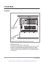
Example:
The device address is 36, inputs I
0
to I
4
belong to Section A,
inputs I
5
to I
7
belong to Section B.
So, taking I
5
as an example: Address of I
5
= 36
.
[5 + (Offset 16)] = 36.21
Output addresses:
Input addresses:
O
0
→
A36.00
I
0
→
E36.00
O
1
→
A36.01
I
1
→
E36.01
O
2
→
A36.02
I
2
→
E36.02
O
3
→
A36.03
I
3
→
E36.03
O
4
→
A36.04
I
4
→
E36.04
O
5
→
A36.05
I
5
→
E36.21
O
6
→
A36.06
I
6
→
E36.22
O
7
→
A36.07
I
7
→
E36.23
Supply voltage
Two supply voltages can be connected to the PSS SB DI8O8: the “Supply”
feeds the module electronics and dedicated test pulse outputs, while the
“Load Supply” feeds the outputs. Both supply voltages have a common
earth.
The “Load Supply” must be connected, even if the outputs on the unit will
not be used. If it is not connected, Section A will remain in a STOP
condition (see section entitled “Operation of the module on SafetyBUS p”).
The advantage in separating the two supply voltages “Supply” and “Load
Supply” is best seen in the following example.
Several machines are secured by the same safety devices. Each of these
machines is assigned a PSS SB DI8O8 module. One power supply feeds
all the “Supply” modules and the general safety devices. Each machine
also has a separate supply voltage, “Load Supply”.
Each unit is configured so that I/Os that are specific to a particular
machine are combined into one I/O group. Inputs for the safety devices
are combined into one I/O group, which is general to all the DI808
modules.
If one of the machines is no longer required or develops a fault, this
machine can be switched off individually without affecting the safety
devices or stopping the other machines.
If the “Supply” fails or if a general safety device disengages, all the
machines will be switched off.
Section A
Section A
Section B
Artisan Technology Group - Quality Instrumentation ... Guaranteed | (888) 88-SOURCE | www.artisantg.com


