Operating Manual
15
Commissioning
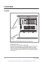
General guidelines are given below, but you should always refer to the
“PSS SB DI8O8 Installation Manual” (this is part of the “Safety BUS p”
System Manual and is also enclosed with every Safety BUS p-compatible
PSS):
• Install the module
INFORMATION
If the module is attached to an earthed DIN rail, this will automatically
cover the module's functional earth requirements.
• Wire the inputs and outputs
• Connect the module to SafetyBUS p and set the device address
• Connect the supply voltage.
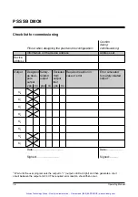
• NOTICE
Every safety-related positive-switching output should undergo an error
simulation: wait until the user program sets the output to “1” (output’s
LED will light) and then generate a short circuit between the output and
24 V. The required error reaction should then occur. This is the only way
to check whether an output has been incorrectly excluded from the
output test and whether the output test that has been programmed is
effective.
Recommissioning
NOTICE
If the device has to be recommissioned you may experience errors when
inserting the terminal blocks, as these are not designed to be exchanged.
To ensure such errors are eliminated, always carry out a function test
when recommissioning.
Faults
If a module is defective or there is a wiring error,
all the outputs in the
affected I/O group will be switched off and the I/O-group will switch to a
STOP condition. An error telegram will then be stored on SafetyBUS p and
the error will entered in the PSS SB DI8O8 error buffer.
An error message will appear on the PSS master’s display. The error stack
display in the system software can be used to locate the error (see
“SafetyBUS p System Description”).
Artisan Technology Group - Quality Instrumentation ... Guaranteed | (888) 88-SOURCE | www.artisantg.com


