Function description
Operating Manual PSS u2 ES 4IOL
1004880-EN-01
10
4
Function description
4.1
Process data
}
The size of the IO-Link master's process image is variable. It depends on the size of the
process image of the devices that are used.
}
The IO-Link master's process image of inputs (PII) consists of the PII of the devices and
a 3 Byte header.
}
The IO-Link master's process image of outputs (PIO) consists of the PIO of the devices
and a 3 Byte header.
}
The header always precedes the devices' process data.
}
The maximum size of the process image of inputs (PII), including the header, is 128
Bytes per module and 32 Bytes per port.
}
The maximum size of the process image of outputs (PIO), including the header, is 128
Bytes per module and 32 Bytes per port.
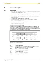
Example of the module's process image
The example below shows the structure of the process image for the IO-Link master mod-
ule. A process image size of 8 Bytes was used for the example. The example uses two IO-
Link sensors, each with a process image size of 2 Bytes and an IO-Link actuator with a pro-
cess image size of 1 Byte. Unused bytes are filled with zeros.
Port 2
Byte 6
Byte 4
Byte 5
Empty
Header
Byte 3
Empty
Empty
Empty
Byte 0...2
Port 0
Byte 6
Byte 4
Byte 5
Empty
Header
Byte 3
Byte 0...2
PII
PIO
Port 0
Port 1
Port 1
Byte 7
Byte 7
Fig.: Example of the module's process image
Legend
PII
Process image of inputs
Header
For details of structure see sections entitled "Header in the process image
of inputs" and "Header in the process image of outputs".
Port 0
IO-Link device with 2 Bytes of input data
Port 1
IO-Link device with 2 Bytes of input data
PIO
Process image of outputs
Port 2
IO-Link device with 1 Byte of output data
Empty
Unused bytes, which are filled with zeros


