Function description
Operating Manual PSS u2 ES 4IOL
1004880-EN-01
12
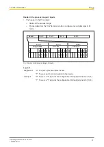
Header in the process image of outputs
}
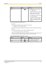
The header in the PIO contains process data from the "CQ" terminal, which is con-
figured as a digital output in DO mode.
Port 1
Port 0
Port 2
Port 3
Header
Not used
Byte 2
CQ output
Port 0
Port 1
Port 2
Port 3
Bit 0
Bit 1
Bit 2
Bit 3
Bit 7
. . .
Byte 1
Port 0
Port 1
Port 2
Port 3
Bit 0
Bit 1
Bit 2
Bit 3
Bit 7
. . .
Byte 0
Not used
Port 0
Port 1
Port 2
Port 3
Bit 0
Bit 1
Bit 2
Bit 3
Bit 7
. . .
Fig.: Header in the process image of outputs
Legend
CQ output
"0": A "0" signal is output at the configurable CQ output (terminal
2,6,10,14).
"1": A "1" signal is output at the configurable CQ output (terminal
2,6,10,14).
4.2
Block diagram
L+0
1
n.c.
3
CQ0
2
L-
4
L+3
13
n.c.
15
CQ3
14
L-
16
IO-Link Port 0
IO-Link Port 3
Module
Supply
Data
(ST)
Periphery
Supply
+24 V DC
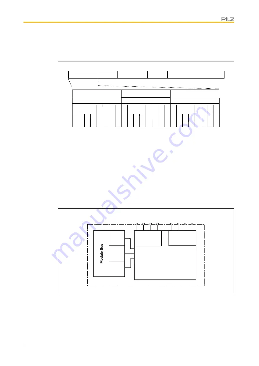
Fig.: Block diagram PSS u2 ES 4IOL


