Wiring
Operating Manual PSS u2 ES 4IOL
1004880-EN-01
22
8
Wiring
8.1
General wiring guidelines
Please note:
}
Signal lines do not have to be shielded.
8.1.1
Connection mechanism for terminal blocks
Procedure:
}
Use a flat head screwdriver.
}
Strip the wire back 9 mm.
}
Feed the stripped cable as far as it will go into the opening for the spring-loaded ter-
minal.
}
Check that the cable is firmly seated.
Please note:
}
The minimum cable cross section for field connection terminals on the terminal blocks
is 0.15 mm
2
(AWG26).
}
The maximum cable cross section for field connection terminals on the terminal blocks
is 1.5 mm
2
with ferrules (AWG14)
}
Use copper wiring.
8.2
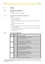
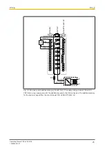
Terminal configuration
Port
Ter-
minal
Terminal configuration
1
1
24 V+ voltage output for sensor/actuator L+
2
IO-Link communication CQ
3
n.c.
4
0 V voltage output for sensor/actuator L-
2
5
24 V+ voltage output for sensor/actuator L+
6
IO-Link communication CQ
7
n.c.
8
0 V voltage output for sensor/actuator L-
3
9
24 V+ voltage output for sensor/actuator L+
10
IO-Link communication CQ
11
n.c.
12
0 V voltage output for sensor/actuator L-
4
13
24 V+ voltage output for sensor/actuator L+
14
IO-Link communication CQ
15
n.c.
16
0 V voltage output for sensor/actuator L-

