background image

Introduction

Operating Manual PSS u2 ES 4IOL
1004880-EN-01

5

1

Introduction

1.1

Validity of documentation

This operating manual explains the function and operation, describes the installation and
provides guidelines on how to connect the product.
This documentation is valid for the product PSS u2 ES 4IOL. It is valid until new document-
ation is published.

1.2

Using the documentation

This document is intended for instruction. Only install and commission the product if you
have read and understood this document. The document should be retained for future ref-
erence.
Please refer to the PSS u2 Installation Manual.

1.3

Definition of symbols

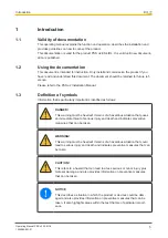
Information that is particularly important is identified as follows:

DANGER!

This warning must be heeded! It warns of a hazardous situation that poses
an immediate threat of serious injury and death and indicates preventive
measures that can be taken.

WARNING!

This warning must be heeded! It warns of a hazardous situation that could
lead to serious injury and death and indicates preventive measures that can
be taken.

CAUTION!

This refers to a hazard that can lead to a less serious or minor injury plus
material damage, and also provides information on preventive measures
that can be taken.

NOTICE

This describes a situation in which the product or devices could be dam-
aged and also provides information on preventive measures that can be
taken. It also highlights areas within the text that are of particular import-
ance.

Summary of Contents for PSS u2

Page 1: ...PSS u2 ES 4IOL Operating Manual 1004880 EN 01 Control system PSS u2 Remote I O system PSS u2...

Page 2: ...nta tion will be gratefully received Source code from third party manufacturers or open source software has been used for some components The relevant licence information is available on the Internet...

Page 3: ...3 Supply 13 4 4 PROFINET 13 4 5 EtherNet IP 13 4 6 Reaction time 14 4 7 Configuration options 14 Section 5 Exchanging an IO Link device 16 Section 6 Exchanging a master 17 Section 7 Installation 18 7...

Page 4: ...Contents Operating Manual PSS u2 ES 4IOL 1004880 EN 01 4 Section 10 Technical details 29 Section 11 Order reference 31 11 1 Product 31 11 2 Accessories 31...

Page 5: ...f symbols Information that is particularly important is identified as follows DANGER This warning must be heeded It warns of a hazardous situation that poses an immediate threat of serious injury and...

Page 6: ...Introduction Operating Manual PSS u2 ES 4IOL 1004880 EN 01 6 INFORMATION This gives advice on applications and provides information on special fea tures...

Page 7: ...s and is used to connect the field wiring Details of the terminal blocks that can be used are available under Intended Use 2 1 Module features The product has the following features IO Link master in...

Page 8: ...ported by PASconfig from version 3 0 0 We recommend that you always use the latest version download from www pilz com 3 3 Safety regulations 3 3 1 Use of qualified personnel The products may only be a...

Page 9: ...it is intended Damage can be attributed to not having followed the guidelines in the manual Operating personnel are not suitably qualified Any type of modification has been made e g exchanging compon...

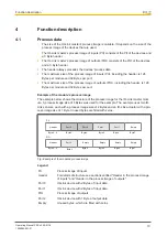
Page 10: ...module s process image The example below shows the structure of the process image for the IO Link master mod ule A process image size of 8 Bytes was used for the example The example uses two IO Link...

Page 11: ...CQ input Port 0 Port 1 Port 2 Port 3 Bit 0 Bit 1 Bit 2 Bit 3 Bit 7 Byte 1 Port 0 Port 1 Port 2 Port 3 Bit 0 Bit 1 Bit 2 Bit 3 Bit 7 Byte 0 Diagnostics Port 0 Port 1 Port 2 Port 3 Bit 0 Bit 1 Bit 2 Bit...

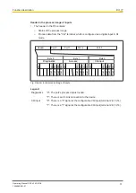
Page 12: ...Bit 3 Bit 7 Byte 1 Port 0 Port 1 Port 2 Port 3 Bit 0 Bit 1 Bit 2 Bit 3 Bit 7 Byte 0 Not used Port 0 Port 1 Port 2 Port 3 Bit 0 Bit 1 Bit 2 Bit 3 Bit 7 Fig Header in the process image of outputs Legen...

Page 13: ...or the input and output data Input data Output data Input and output data 8 Byte 8 Byte 8 Byte 16 Byte 16 Byte 16 Byte 32 Byte 32 Byte 32 Byte 64 Byte 64 Byte 64 Byte 128 Byte 128 Byte 128 Byte INFORM...

Page 14: ...l ST input The CQ terminal can be configured as an ST in put for each port The input current can also be configured for the ST inputs in DI mode DO mode The port is used as a digital ST output The CQ...

Page 15: ...description Operating Manual PSS u2 ES 4IOL 1004880 EN 01 15 Download In this mode the configuration saved in the master is written to the device This setting can be used when a device needs to be ex...

Page 16: ...configuration has already been saved in the IO Link master Upload set ting The master port containing the device to be exchanged has been configured as follows Operating mode Fixedmode Save the devic...

Page 17: ...odule on to the backplane Procedure if Download has been set at one or more ports under Save the device configuration 1 Remove the terminal block from the master module 2 Disconnect the master module...

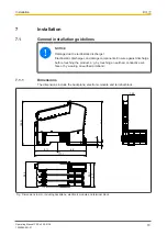
Page 18: ...arge can damage components Ensure against discharge before touching the product e g by touching an earthed conductive sur face or by wearing an earthed armband 7 1 1 Dimensions The dimensions include...

Page 19: ...ck has been removed first The mechanics of the electronic modules are designed for 20 plug in out cycles On electronic modules with outputs the terminal block may only be inserted and re moved when th...

Page 20: ...S 4IOL 1004880 EN 01 20 2 Swivel the electronic module downwards until you hear it click into place 3 Insert the terminal block into the suspen sion lug on the module 4 Swivel the terminal block upwar...

Page 21: ...rds 7 2 3 Changing an electronic module during operation An electronic module can be hot swapped Effects Module bus communication between the other modules is not interrupted The configuration data is...

Page 22: ...WG26 The maximum cable cross section for field connection terminals on the terminal blocks is 1 5 mm2 with ferrules AWG14 Use copper wiring 8 2 Terminal configuration Port Ter minal Terminal configura...

Page 23: ...Wiring Operating Manual PSS u2 ES 4IOL 1004880 EN 01 23 8 2 1 Connection examples 16 IO Link Device L CQ L Fig IO Link device Class A Port 16 L CQ Fig 1 channel sensor in DI mode...

Page 24: ...Wiring Operating Manual PSS u2 ES 4IOL 1004880 EN 01 24 16 L CQ Fig 1 channel actuator in DO mode...

Page 25: ...ice L CQ ES PSP ES 8PTD 24V 0V 16 24 V 0 V ES 4IOL Fig IO Link device with additional supply Class B Port The supply voltage module PSS u2 ES PSP forms a new supply group for the additional supply to...

Page 26: ...d to the head module and will be entered in the head module s diagnostic log 9 1 Display elements and messages 1 2 1 L 0 CQ0 n c L 1 n c L 2 n c L 3 n c CQ1 CQ2 CQ3 Port 0 Port 1 Port 2 Port 3 n c n c...

Page 27: ...overtemperature Too warm If the module temperature exceeds a threshold value then a warning is sent to the head module If the temperature drops back below the threshold value the module sends an all...

Page 28: ...inactive Green Terminal error e g device miss ing or wrong device Only the CQ terminal status display for the affected terminal flashes Temperature errror too hot or undervoltage All CQ terminal stat...

Page 29: ...Link revision 1 1 Communication speed COM1 COM2 COM3 Max cable length 20 m Min cycle time dynamic and dependent on the payload length 2 ms Max size of input process data per port 32 Byte Max size of o...

Page 30: ...equency 8 4 150 Hz Amplitude 0 35 mm Acceleration 10 m s Shock stress In accordance with the standard EN 60068 2 27 Acceleration 150 m s Duration 11 ms Airgap creepage In accordance with the standard...

Page 31: ...der No PSS u2 A LC E1 10 pcs Label holder 23 5 x 10 5 mm 10 pieces 328 910 PSS u2 A LC E2 10 pcs Label holder 103 x 10 5 mm 10 pieces 328 911 PSS u2 A LA E1 10 pcs Labelling strips 23 5 x 10 5 mm 10 x...

Page 32: ...tyNET p THE SPIRIT OF SAFETY are registered and protected trademarks of Pilz GmbH Co KG in some countries We would point out that product features may vary from the details stated in this document dep...

Reviews: