Installing the PSSu system
Installation Manual PSSuniversal
21262-EN-07
19
}
The first digit denotes a base module's connection column (e.g.: connection
2
3 is in the
second column).
}
The second digit denotes a base module's connection level (e.g.: connection 2
3
is in
the third level).
The function of the base module connections depends on the electronic module.
4.3.1.1
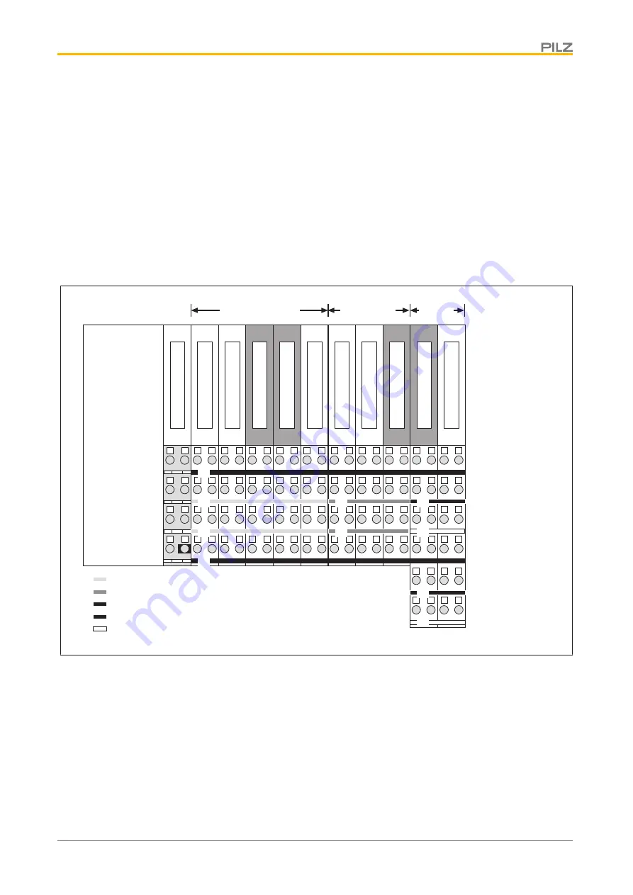
Colour marking on the connection levels
The colour marking on the connection levels is a wiring aid. Various colour markers are
available for labelling. The colour markers can be used to label different supplies. This way
the connection levels remain clearly visible, even after wiring.
Example:
Head Module
21
11
22
12
23
13
24
14
Power Supply
21
11
22
12
23
13
24
14
PSSu E S 4DI
21
11
22
12
23
13
24
14
PSSu E F 2DO 2
21
11
22
12
23
13
24
14
PSSu E S 4AI U
21
11
22
12
23
13
24
14
PSSu E S 2DO 2
21
11
22
12
23
13
24
14
PSSu E S 4AO U
21
11
22
12
23
13
24
14
PSSu E F 4DI
21
11
22
12
23
13
24
14
PSSu E S 4DI
21
11
22
12
23
13
24
14
PSSu E F 4DI
Connection level
1
Connection level
2
Connection level
3
Connection level
4
[1] : + 24V DC Periphery Supply
[2] : 0 V DC Periphery Supply
[4] :
Inputs/outputs
21
11
22
12
23
13
24
14
PSSu E F 4DI
21
11
22
12
23
13
24
14
PSSu E F 2DO 2
Digit. Output
Digital Input
[2]
25
15
26
16
25
15
26
16
[5] :
Cable screening
Connection level
5
Connection level
6
Analog
[2]
[5]
[5]
[3]
[4]
[4]
[1]
[1]
[3] : 0 V DC Analog
[3]
4.3.2
Connections on the compact modules
The connections on the compact modules are divided into terminal rows. Single or three-
row connectors with spring-loaded terminals can be plugged into the device's single-row
10-pin connector strip.
The function of the connections depends on the compact module.
}
Terminal row 1
Connection of the inputs and outputs, periphery supply (24 V and 0 V).


