background image


5 minute guide

02


12


En


Using the Quick Setup


You can use the Quick Setup to get your 
system up and running with just a few button 
presses. The receiver automatically makes 
the necessary settings after you have selected 
your speaker setup, room size and listening 
position. 

If you want to make more specific settings, 
refer to 


Choosing your receiver setup


 on 

page 42. 

Use the front panel controls for the steps 
below.


VSX-D914 model only


 – Note that you don’t 

have to make these settings if you use the 
automatic MCACC setup instead (in this 
case, go straight to the 


Quick surround sound 

setup


 on page 14).


1

If the receiver is off, press 


 STANDBY/ON to turn the power on.

2

Press QUICK SETUP.

SW DET


 flashes in the display while the 

receiver checks your setup for a subwoofer. 


SW YES


 or 


SW NO


 confirms the subwoofer 

check, then the display prompts you to select 
your speaker setup.


3

Use the MULTI JOG dial to choose your 

speaker setup.


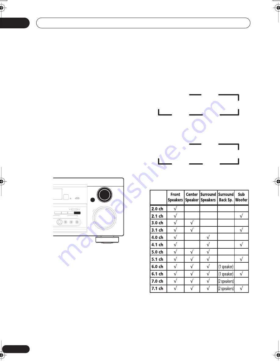
When a subwoofer was detected in step 2, you 
can cycle between the following choices:

If a subwoofer wasn’t detected in step 2, you 
can cycle between the following choices:

• Check the table below to find the speaker 

setup that corresponds with your system.


4

Press ENTER.

5

Use the MULTI JOG dial to choose your 

room size.


Depending on the distance of your speakers 
from the listening position, choose between 
small, medium, or large (


S


M


 or 


L


), 


M


 being 

an average-sized room.

UP

DOWN

MULTI  JOG

MASTER VOLUME

ENTER

SPEAKERS

S-VIDEO

VIDEO

L AUDIO R

SB CH
MODE

TONE

QUICK  SETUP

VIDEO INPUT

MULTI JOG

7.1ch

4.1ch

6.1ch

5.1ch

2.1ch

3.1ch

7.0ch

4.0ch

6.0ch

5.0ch

2.0ch

3.0ch

VSX_D912.book.fm 12 ページ 2003年12月5日 金曜日 午前9時43分

Summary of Contents for 814 - Steiner 10x44 Peregrine XP Binocular

Page 1: ...AUDIO VIDEO MULTI CHANNEL RECEIVER VSX D814 VSX D914 Operating Instructions ...

Page 2: ...PREVENT ELECTRIC SHOCK DO NOT USE THIS POLARIZED PLUG WITH AN EXTENSION CORD RECEPTACLE OR OTHER OUTLET UNLESS THE BLADES CAN BE FULLY INSERTED TO PREVENT BLADE EXPOSURE ATTENTION POUR PREVENIR LES CHOCS ELECTRIQUES NE PAS UTILISER CETTE FICHE POLARISEE AVEC UN PROLONGATEUR UNE PRISE DE COURANT OU UNE AUTRE SORTIE DE COURANT SAUF SI LES LAMES PEUVENT ETRE INSEREES A FOND SANS EN LAISSER AUCUNE PAR...

Page 3: ...ctrician to replace your obsolete outlet Do not defeat the safety purpose of the grounding type plug POWER CORD PROTECTION Power supply cords should be routed so that they are not likely to be walked on or pinched by items placed upon or against them paying particular attention to cords at plugs convenience receptacles and the point where they exit from the product OUTDOOR ANTENNA GROUNDING If an ...

Page 4: ...tems 22 Hints on speaker placement 22 Connecting additional amplifiers 24 AC outlet 25 Operating other Pioneer components 25 Using this receiver with a Pioneer plasma display 26 05 Controls and displays Front panel 27 Display 29 Remote control 31 06 Listening to your system Listening in surround sound 35 Using the Advanced surround effects 35 Listening in stereo 36 Choosing the input signal 37 Usi...

Page 5: ...o a station 53 Saving station presets 54 Naming station presets 54 Listening to station presets 55 09 Making recordings Making an audio or a video recording 56 10 Controlling the rest of your system Setting the remote to control other components 57 Selecting preset codes directly 57 Programming signals from other remote controls 58 Erasing one of the remote control button settings 59 Erasing all o...

Page 6: ...helf etc be sure to leave more than 8 inches 20 cm of space above the receiver Making cable connections Make sure not to bend the cables over the top of this unit as shown in the illustration If this happens the magnetic field produced by the transformers in this unit may cause a humming noise from the speakers Loading the batteries Incorrect use of batteries may result in such hazards as leakage ...

Page 7: ...g range of remote control unit The remote control may not work properly if There are obstacles between the remote control and the receiver s remote sensor Direct sunlight or fluorescent light is shining onto the remote sensor The receiver is located near a device that is emitting infrared rays The receiver is operated simultaneously with another infrared remote control unit 30 30 23ft 7m ...

Page 8: ...r room but also on the source and the sound settings of the receiver DVD Video has become the basic source material for home theater due to its size quality and ease of use Depending on the DVD you can have up to seven different audio tracks coming from one disc all of them being sent to different speakers in your system This is what creates a surround sound effect and gives you the feeling of bei...

Page 9: ...2 Hook up your TV Use a video cord to connect your receiver to the TV using the jacks as shown below ASSIGNABLE A MONITOR OUT Y PB PR Y PB PR DVR VCR TV SAT DVD LD CONTROL OUT IN AM LOOP FM UNBAL 75 Ω IN IN IN IN IN IN COMPONENT VIDEO MONITOR OUT MONITOR OUT SUB WOOFER SURROUND CEN TER S VIDEO OUT OUT VIDEO SUB WOOFER R AUDIO L IN IN IN IN IN OUT DIGITAL OUT OUT IN OPT OPT COAX COAX OPT AUX CD L R...

Page 10: ...e center speaker C connect the CENTER PREOUT jack on this unit to the audio input jack on your TV In this case the center speaker shown is unnecessary If you are using only one surround back speaker connect the positive wire to the right channel terminal and the negative wire to the left channel terminal shown below ASSIGNABLE AC OUTLET MONITOR OUT Y PB PR Y PB PR DVR VCR TV SAT DVD LD CONTROL OUT...

Page 11: ... Press QUICK SETUP on the front panel to specify your speaker setup room size and listening position Use the MULTI JOG dial to select and ENTER to confirm your selection See Using the Quick Setup on page 12 if you re unsure about the settings VSX D914 model only For a more complete surround sound setup we recommend using the automatic MCACC setup in the Quick surround sound setup on page 14 6 Play...

Page 12: ...flashes in the display while the receiver checks your setup for a subwoofer SW YES or SW NO confirms the subwoofer check then the display prompts you to select your speaker setup 3 Use the MULTI JOG dial to choose your speaker setup When a subwoofer was detected in step 2 you can cycle between the following choices If a subwoofer wasn t detected in step 2 you can cycle between the following choice...

Page 13: ...If you are nearer to the front speakers than the surround speakers MID If you are equal distance from the front and surround speakers BACK If you are nearer to the surround speakers than the front speakers 8 Press ENTER to confirm your setup The display shows the speaker setup room size and listening position that you have selected MID BACK FWD ...

Page 14: ...chair Make sure there are no obstacles between the speakers and the microphone 3 If the receiver is off press STANDBY ON to turn the power on 4 If you have a subwoofer turn it on 5 Press RECEIVER 6 Press MCACC SETUP Try to be as quiet as possible after pressing MCACC SETUP The system outputs a series of test tones to establish the ambient noise level If the noise level is too high NOISY blinks in ...

Page 15: ...evel If you have connected a subwoofer it will check for ambient noise once again When the auto surround setup is complete the volume level returns to normal and COMPLETE then RESUME shows in the display The MCACC indicator then lights to show that MCACC setup is complete If the room environment is not optimal for the auto surround setup too much ambient noise echo off the walls obsta cles blockin...

Page 16: ...are hooking up Be sure to insert completely Component video cords Use component video cords to get the best possible color reproduction of your video source The color signal of the TV is divided into the luminance Y signal and the color PB and PR signals and then output In this way interference between the signals is avoided Connect from the component video jacks on the rear of the receiver to the...

Page 17: ... The arrows indicate the direction of the signal If you have an LD player you need to make special connections to ensure you can play 2 RF format LDs on your system If this is the case hook up your DVD or LD player directly to an RF demodulator using both the 2 RF output and either a coaxial or optical digital connection We also recommend hooking up your digital components to analog audio jacks as...

Page 18: ...of the signal ASSIGNABLE MONITOR OUT Y PB PR Y PB PR DVR VCR TV SAT DVD LD CONTROL OUT IN AM LOOP FM UNBAL 75 Ω IN IN IN IN IN IN COMPONENT VIDEO MONITOR OUT MONITOR OUT SUB WOOFER SURROUND CEN TER S VIDEO OUT OUT VIDEO SUB WOOFER R AUDIO L IN IN IN IN IN OUT DIGITAL OUT OUT IN OPT OPT COAX COAX OPT AUX CD L R DVR VCR TV SAT TV SAT DVR VCR DVD LD CD DVD LD PLAY CD R TAPE MD FRONT PREOUT ASSIGNABLE...

Page 19: ...ed via the front panel using the VIDEO button There are standard audio video jacks as well as an S video jack and an optical input Hook them up the same way you made the rear panel connections ASSIGNABLE MONITOR OUT Y PB PR Y PB PR DVR VCR TV SAT DVD LD CONTROL OUT IN AM LOOP FM UNBAL 75 Ω IN IN IN IN IN IN COMPONENT VIDEO MONITOR OUT MONITOR OUT SUB WOOFER SURROUND CEN TER S VIDEO OUT OUT VIDEO S...

Page 20: ...insert into the hole then snap the connector shut Using external antennas To improve FM reception Use an F connector to connect an external FM antenna To improve AM reception Connect a 15 18 feet length of vinyl coated wire to the AM antenna terminal without disconnecting the supplied AM loop antenna For the best possible reception suspend hori zontally outdoors DVR VCR TV SAT DVD LD CONTROL OUT I...

Page 21: ...ee Switching the speaker impedance on page 67 if you plan to use speakers with an impedance of less than 8Ω Be sure to complete all connections before connecting this unit to the AC power source ASSIGNABLE AC OUTLET MONITOR OUT Y PB PR Y PB PR DVR VCR TV SAT DVD LD CONTROL OUT IN AM LOOP FM UNBAL 75 Ω IN IN IN IN IN IN COMPONENT VIDEO MONITOR OUT MONITOR OUT SURROUND CEN TER S VIDEO OUT OUT VIDEO ...

Page 22: ...he receiver 3 Tighten terminal The speaker terminals also accept single banana plugs Refer to speaker manual for details A and B speaker systems The receiver has two speaker systems A and B A is the main system supporting the full speaker setup If you switch on both A and B speaker systems only the front speakers and the active subwoofer will be audible No sound will come from the center surround ...

Page 23: ...e front and center speakers Doing so can weaken the surround sound effect To achieve the best possible surround sound install your speakers as shown below Be sure all speakers are installed securely to prevent accidents and improve sound quality If you choose to install the center speaker on top of the TV be sure to secure it with putty or by other suitable means to reduce the risk of damage or in...

Page 24: ... using a subwoofer change the front speaker setting see Speaker setting on page 43 to large SIGNABLE AC OUTLET PB PR ø SAT IN LD IN PREOUT B R R R L R L FRONT SURROUND L L L RROUND BACK SINGLE FRONT CENTER SURROUND BACK SURROUND SEEINSTRUCTION MANUAL DVR VCR TV SAT DVD LD CONTROL OUT IN AM LOOP FM UNBAL 75 Ω IN IN IN IN IN IN MONITOR OUT MONITOR OUT S VIDEO OUT OUT VIDEO SUB WOOFER R AUDIO L IN IN...

Page 25: ... or an electric shock Do not place the unit a piece of furniture etc on the power cord or pinch the cord Never make a knot in the cord or tie it with other cords The power cords should be routed such that they are not likely to be stepped on A damaged power cord can cause a fire or give you an electrical shock Check the power cord once in a while When you find it damaged ask your nearest Pioneer a...

Page 26: ...escribed in this chapter For each component connect the video output directly to the plasma display and just connect the audio analog and or digital to this receiver The 3 ringed SR cable from Pioneer is commercially available under the part number ADE7095 Contact the Pioneer Customer Support division for more infor mation on obtaining an SR cable DVR VCR TV SAT DVD LD CONTROL OUT IN AM LOOP FM UN...

Page 27: ...pressing TONE QUICK SETUP or TUNER EDIT 7 MASTER VOLUME 8 PHONES jack Use to connect headphones When the head phones are connected there is no sound output from the speakers UP DOWN MULTI JOG MASTER VOLUME ENTER AUDIO VIDEO MULTI CHANNEL RECEIVER VSX D914 STANDBY ON PHONES DVD LD TV SAT DVR VCR VIDEO CD CD R TAPE MD TUNER AUX STATION STANDARD SPEAKERS S VIDEO MCACC DIGITAL IN SETUP MIC VIDEO VIDEO...

Page 28: ...nge the speaker impedence Switching the speaker impedance on page 67 15 SB CH MODE Selects the Surround back channel mode page 38 16 TONE Press this button to access the bass and treble controls which you can then adjust with the MULTI JOG dial 17 QUICK SETUP See Using the Quick Setup on page 12 18 VIDEO INPUT See Connecting to the front panel video terminal on page 19 19 DIGITAL IN See Connecting...

Page 29: ...e STANDARD mode of the receiver is on this lights to indicate decoding of a Dolby Digital signal 4 2 PRO LOGIC II x When the STANDARD Pro Logic II mode of the receiver is on this lights to indicate Pro Logic II decoding The x lights to indicate Pro Logic IIx decoding see Listening in surround sound on page 35 for more on this 5 VIR SB Lights during Virtual surround back processing 6 DIRECT Lights ...

Page 30: ...ts when LOUDNESS has been selected 15 TUNER indicators STEREO Lights when a stereo FM broadcast is being received in auto stereo mode MONO Lights when the mono mode is set using the MPX button TUNED Lights when a broadcast is being received 16 Master volume level Shows the overall volume level dB indi cates the minimum level and 0 dB indicates the maximum level Depending on your level settings for...

Page 31: ...e on off 5 Tuner component control buttons MCACC The following button controls except MCACC SETUP can be accessed after you have selected the corresponding MULTI CONTROL button TUNER DVD TV SAT etc D ACCESS After pressing you can access a radio station directly using the number buttons page 53 TOP MENU Displays the disc top menu of a DVD DTV MENU Displays menus on a digital TV T EDIT Press to memo...

Page 32: ...CONTROL button If you have two TVs assign the main TV to the TV CONT button TV Use to turn on off the power of the TV TV VOL Use to adjust the volume on your TV INPUT SELECT Use to select the TV function TV CH Use to select channels 8 Component control buttons The main buttons etc are used to control a component after you have selected it using the MULTI CONTROL buttons The controls above these bu...

Page 33: ...speaker when setting up the surround sound of the receiver page 50 LEVEL Adjusts the levels of the surround sound of the receiver page 50 EFFECT Adds or subtracts the amount of effect with different advanced surround modes page 35 10 SHIFT Press to access the DVR controls above the component control butttons 11 SOURCE Press to turn on off other components connected to the receiver 12 Character dis...

Page 34: ...ECEIVER Switches the remote to control the receiver used to select the features above the number buttons INPUT ATT etc Also use this button to set up surround sound page 42 page 49 page 50 14 MASTER VOLUME Use to set the listening volume ...

Page 35: ...nnel sound espe cially suited to music sources You can t use the STANDARD mode with 96kHz PCM or DTS 96kHz 24 bit stereo sources During playback of a Dolby Digital multi channel source with the SB CH MODE switched ON you will only be able to select DOLBY EX or 2 Pro Logic IIx MUSIC See Using the Surround Back Channel SB CH on page 38 for more on this Using the Advanced surround effects The Advance...

Page 36: ...the sound mode you have selected you may not get sound from the surround back speakers in your setup For more on this refer to Using the Surround Back Channel SB CH on page 38 If you press ADV SURR when the head phones are connected the PHONES SURROUND mode will automatically be selected You can t use the Advanced Surround listening modes with 96kHz PCM or DTS 96kHz 24 bit sources The Advanced Sur...

Page 37: ...uts DIGITAL Selects the digital input When set to DIGITAL or AUTO 2 DIGITAL lights when a Dolby Digital signal is input and DTS lights when a DTS signal is input This receiver can only play back Dolby Digital PCM 32kHz 96 kHz and DTS digital signal formats including DTS 96kHz 24 bit With other digital signal formats set to ANALOG You may get digital noise when a LD or CD player compatible with DTS...

Page 38: ...hear the surround back channel Press SB CH MODE front panel repeatedly to cycle the surround back channel options Each press cycles through the options as follows You can t use the surround back channel with headphones the STEREO DIRECT mode or if the Surround back speaker setting on page 44 is SB SW or SB You can t hear the surround back channel with DTS 96kHz 24 bit sources SB OFF SB ON SB AUTO ...

Page 39: ...cycle the virtual surround back channel options Each press cycles through the options as follows You can t use the Virtual Surround Back mode with headphones the STEREO DIRECT mode or if the Speaker setting on page 43 is set to S You can only use the Virtual Surround Back mode if the surround speakers are on and the Surround back speaker setting on page 44 is set to SB or SB SW You can t adjust th...

Page 40: ... change the amount of bass or treble as necessary Wait about five seconds for your changes to be input automatically You can only use the tone controls when STEREO DIRECT is selected DIRECT will switch to STEREO when the tone controls are used The tone controls affect SPEAKER A only They can t be used when SPEAKER A is switched off Playing other sources 1 Turn on the power of the playback componen...

Page 41: ... levels can be set Using the sleep timer The sleep timer switches the receiver into standby after a specified amount of time so you can fall asleep without worrying about the receiver being left on all night Use the remote control to set the sleep timer Press SLEEP repeatedly to set the sleep time You can check the remaining sleep time at any time by pressing SLEEP once Pressing repeatedly will cy...

Page 42: ... each option as you cycle through the display Speaker setting page 43 Specify the number and type of speakers you have connected Surround back speaker setting page 44 Specify your surround back speaker surround back subwoofer setup Subwoofer setting page 44 Specify how the subwoofer is used Crossover frequency setting page 44 Determine which frequencies will be sent to the subwoofer or large speak...

Page 43: ... 2 setting Optical digital input 1 setting Optical digital input 2 setting SR control settings page 48 Specify how you want to control your Pioneer plasma display Control mode setting Volume control setting Function setting for DVD input Function setting for TV input Function setting for DVR input Function setting for VIDEO input 3 Use or to adjust the setting The setting is entered automatically ...

Page 44: ...PLUS setting for extra bass Use or to select the subwoofer setting YES The LFE channel and bass frequen cies from the small S speakers are sent to the subwoofer PLUS The LFE channel and bass frequencies from all speakers are sent to the subwoofer L speakers will also output bass NO No bass frequencies are sent to the subwoofer If you chose the small front speaker setting SW YES is automatically se...

Page 45: ...he ultra low bass tones from distorting the sound from the speakers Use or to set the attenuation level 0 dB 10 dB or dB When is selected appears in the display LFE is not available Front left speaker distance setting Default setting 10 ft Sets the distance from the front left speaker to the listening position Use or to set the distance of the front left speaker from the main listening position wi...

Page 46: ...ng the surround speaker distance can t be set Surround back speaker distance setting Default setting 10 ft You should set the distance of the surround back speakers accurately to hear sounds coming from all speakers at the same time Use or to set the distance of the surround back speakers from the main listening position within the range of 0 5 ft to 45 ft When SB or SB SW is selected in the surro...

Page 47: ...tting you can choose which channel in the dual mono setting you want to listen to If Dolby Digital mode is switched on you will hear the channel you have selected either ch1 or ch2 through your center speaker With Dolby Digital mode off or if you don t have a center speaker you will hear the channel you have selected through both front speakers In the Lch1 Rch2 setting the left front speaker will ...

Page 48: ...ust be switched to SR ON to access the settings below default is SR OFF SR OFF Switches SR off the receiver and plasma display work independently SR ON Switches SR on the receiver sends control signals to the plasma display Volume control setting VOL C OFF The receiver does not control the volume of the plasma display VOL C ON When the receiver is switched to one of the inputs that use the plasma ...

Page 49: ... page 43 before using the MCACC setup VSX D914 model only The microphone provided with your system must be disconnected from the front panel to to use the MCACC manual setup These test tones can be loud so take care that there is no one in the room who will be startled by the noise 1 Press RECEIVER 2 Press MCACC SETUP The MCACC system uses the left front speaker as a reference point to calibrate t...

Page 50: ...MCACC system to set up your speaker system will overwrite any previous settings you had for the STANDARD or ADVANCED SURROUND modes Setting separate channel levels for listening modes Default setting 0 dB In addition to the MCACC setup you can also set relative channel levels from the listening position using the method below Using CH SELECT see tip below it is also possible to set separate channe...

Page 51: ... the subwoofer transmits an ultra low frequency its sound may seem quieter than it actually is Using test tones to set up your speaker system will overwrite any previous settings you had for the STANDARD or ADVANCED SURROUND modes Using the SR mode with a Pioneer plasma display When connected using an SR cable a number of features become available to make using this receiver with your Pioneer plas...

Page 52: ...a displays on page 48 You can also use the System Setup menu to switch the SR mode of the receiver If you disconnect the SR cable or switch the plasma display off while SR is on the receiver will automatically revert to SR OFF SR ERR shows in the display if no SR connection is detected for example the cable isn t connected ...

Page 53: ...me press TUNE High speed tuning Press and hold TUNE for high speed tuning Release the button at the frequency you want Improving FM stereo sound If the TUNED or STEREO indicators don t light when tuning to an FM station because the signal is weak press the MPX button to switch the receiver into mono reception mode This should improve the sound quality and allow you to enjoy the broadcast Tuning di...

Page 54: ...e of the three classes then press ST STATION to select the station preset you want You can also use the the MULTI JOG dial front panel to select a station preset 4 Press ENTER After pressing ENTER the preset class and number stop blinking and the receiver stores the station Naming station presets For easier identification you can name your station presets 1 Choose the station preset you want to na...

Page 55: ... four spaces instead of a name Once you have named a station preset you can press TUNER DISPLAY when listening to a station to switch the display between the name and the frequency Listening to station presets You will need to have some presets stored to do this See Saving station presets on page 54 if you haven t done this already 1 Press TUNER to select the tuner 2 Press CLASS to select the clas...

Page 56: ...SIGNAL SELECT on the front panel to select the input signal corresponding to the source component see page 37 for more on this 3 Prepare the source you want to record Tune to the radio station load the CD video DVD etc 4 Prepare the recorder Insert a blank tape MD video etc into the recording device and set the recording levels Refer to the instructions that came with the recorder if you are unsur...

Page 57: ...TV codes for example codes for TV CATV Satellite TV or DTV can only be assigned to the TV SAT or TV CONT button You can cancel or exit any of the steps by pressing RECEIVER To go back a step press RETURN After one minute of inactivity the remote automatically exits the operation Selecting preset codes directly 1 While pressing the RECEIVER button press and hold the 1 button The remote LCD display ...

Page 58: ...e LCD display shows SETUP 2 Press the MULTI CONTROL button for the component you want to control The LCD on the remote displays the compo nent you want to control You can t assign the RECEIVER button 3 Use and to select LEARN then press ENTER PRES KEY and the LEARN icon show in the LCD display To exit or cancel press RECEIVER 4 Point the two remote controls towards each other then press the button...

Page 59: ...VSX D914 model only This erases one of the buttons you have programmed and restores the button to the factory default 1 While pressing the RECEIVER button press and hold the 1 button The remote LCD display shows SETUP 2 Press the the MULTI CONTROL button corresponding to the button setting to be erased The LCD on the remote displays the compo nent 3 Use and to select ERASE then press ENTER The LCD...

Page 60: ...ct function is on any component you select using the MULTI CONTROL buttons will be selected by both the receiver and the remote control When you turn direct function off you can operate the remote control without affecting the receiver 1 While pressing the RECEIVER button press and hold the 1 button The remote LCD display shows SETUP 2 Press the MULTI CONTROL button for the component you want to c...

Page 61: ...ss to switch the component assigned to the TV CONT button on or off Cable TV Satellite TV TV DTV Switches the DTV on or off DTV Press to get information on DTV programs DTV Use to choose the BLUE commands on a DTV menu DTV Use to choose the YELLOW commands on a DTV menu DTV Use to choose the GREEN commands on a DTV menu DTV Use to choose the RED commands on a DTV menu DTV AUDIO Use to switch DTV a...

Page 62: ...he menu screen Cable TV Satellite TV TV ENTER Press to select or adjust and navigate items on the menu screen Cable TV Satellite TV TV DTV Button s Function Components SOURCE Press to switch the component between standby and on CD MD CD R VCR DVD LD DVR player Cassette deck Press to return to the start of the current track Repeated presses skips to the start of previous tracks CD MD CD R DVD LD pl...

Page 63: ...t track 13 CD MD CD R VCR LD player ENTER DISC Chooses the disc Multiple CD player Ejects the disc MD player Use as the ENTER button VCR Use as the CLEAR button DVD Displays the setup screen for DVR players DVR player Changes sides of the LD LD player TOP MENU Displays the disc top menu of a DVD player DVD DVR player MENU Displays menus concerning the current DVD or DVR you are using DVD DVR playe...

Page 64: ...ys changes the subtitles on multilingual DVDs DVD DVR Player HDD SHIFT CH Switches to the hard disk controls when using a DVD HDD recorder DVR Player DVD SHIFT CH Switches to the DVD controls when using a DVD HDD recorder DVR Player Button s Function Components ...

Page 65: ...automatically take the unit to your nearest Pioneer authorized service center or your dealer for servicing No sound is output when a function is selected Make sure the component is connected correctly refer to Con necting up on page 16 Press MUTE on the remote control to turn muting off No image is output when a function is selected Make sure the component is connected correctly refer to Con necti...

Page 66: ...he subwoofer has a volume knob make sure it s turned up Switch the Subwoofer setting on page 44 to YES or PLUS Switch the LFE attenuator setting on page 45 to 0 dB or 10 dB The Dolby Digital or DTS source you are listening to does not have an LFE channel Noise during playback of a cassette deck Move the cassette deck further from your receiver until the noise disappears Sound is produced from othe...

Page 67: ... the factory default settings Switching the speaker impedance We recommend using speakers of 8Ω with this system but it is possible to switch the impedance setting if you plan to use speakers with a 6Ω impedance rating With the receiver in standby press STANDBY ON while holding down the SPEAKERS button Each time you do this you switch between the impedance settings SP 6 OHM Use this setting if you...

Page 68: ...k 100 W per channel 1kHz 1 0 8 Ω Input Sensitivity Impedance CD DVR VCR CD R TAPE MD DVD LD TV SAT 200 mV 47 kΩ Frequency response CD DVR VCR CD R TAPE MD DVD LD TV SAT 5 Hz to 100 000 Hz dB Output Level Impedance DVR VCR REC CD R TAPE MD REC 200 mV 2 2 kΩ Tone control Bass 6 dB 100 Hz Treble 6 dB 10 kHz Loudness 6 5 dB 3 dB 100 Hz 10 kHz at volume level 50 dB Signal to Noise Ratio IHF short circu...

Page 69: ...CHED Dimensions 420 W x 158 H x 401 D mm 16 9 16 W x 6 1 4 H x 15 13 16 D in Weight without package 10 6 kg 23 4 lb Furnished Parts AM loop antenna 1 FM wire antenna 1 AA LR6 dry cell batteries 2 Remote control 1 Warranty Card 1 Microphone VSX D914 model only 1 Microphone stand VSX D914 model only 1 These operating instructions 1 Specifications and the design are subject to possible modifications ...

Page 70: ...Additional information 11 70 En ...

Page 71: ...ADA INC 300 Allstate Parkway Markham Ontario L3R OP2 Canada TEL 905 479 4411 PIONEER EUROPE NV Haven 1087 Keetberglaan 1 B 9120 Melsele Belgium TEL 03 570 05 11 PIONEER ELECTRONICS ASIACENTRE PTE LTD 253 Alexandra Road 04 01 Singapore 159936 TEL 656 472 1111 PIONEER ELECTRONICS AUSTRALIA PTY LTD 178 184 Boundary Road Braeside Victoria 3195 Australia TEL 03 9586 6300 PIONEER ELECTRONICS DE MEXICO S...

Reviews: