132
PDP-5020FD
1
2
3
4
A
B
C
D
E
F
1
2
3
4
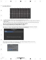
[2-5] PANEL-1 ADJ (+)
This is a page for settings for the driving voltage and AM radio countermeasures. Pressing the ENTER/SET key shifts the
screen to the next nested layer below for item selection.
On third line of the screen, the white balance, ABL table, and drive sequence in the current status are displayed.
(Items that have lower layers are the same.)
When entered to this layer, panel white balance and the gamma setting become the default temporarily for setting
that is necessary for voltage adjustment. Turn off the noise option function.
<DOWN> : Shifting to PANEL-2 ADJ (+)
<UP>
: Shifting to POWER DOWN
<SET>
: Shifting to the next nested layer
g
Key operation
<DOWN> : Shifting to the next item
<UP>
: Shifting to the previous item
<RIGHT> : Adding by one to the adjustment/
setting value
<LEFT>
: Subtracting by one from the
adjustment/setting value
<VOL+> : Adding by 10 to the adjustment/
setting value
<VOL->
: Subtracting by 10 from the
adjustment/setting value
<SET>
: Determining the adjustment/setting
value and shifting to the upper layer
g
Key operation
A
.
P
N E L
W
/
1
[
1
A
6 0 V S ]
F A C T
A
J
P
N E L – 1
A D
)
( +
A
.
P
N E L
W
/
1
[
1
A
6 0 V S ]
F A C T
O
>
V
L
O F
T
F S E
< =
A
J
P
N E L – 1
A D
2
: 1
8
I
–
N 1
3
2
0 6 0
– R G B
H
J
–
B
I
–
N 1
3
2
0 6 0
– R G B
H
J
–
B
1
5
10
15
16
1
5
10
15
20
25
30
32
1
5
10
15
16
1
5
10
15
20
25
30
32
1
2
3
4
5
6
7
8
9
A
B
C
D
E
1
2
3
4
5
6
7
8
9
A
B
C
D
E
AREA
AREA
Summary of Contents for ARP3476
Page 10: ...10 PDP 5020FD 1 2 3 4 A B C D E F 1 2 3 4 2 2 SPECIFICATIONS ...
Page 11: ...11 PDP 5020FD 5 6 7 8 5 6 7 8 A B C D E F ...
Page 12: ...12 PDP 5020FD 1 2 3 4 A B C D E F 1 2 3 4 2 3 PANEL FACILITIES Front Section ...
Page 13: ...13 PDP 5020FD 5 6 7 8 5 6 7 8 A B C D E F Rear Section ...
Page 14: ...14 PDP 5020FD 1 2 3 4 A B C D E F 1 2 3 4 Remote Control Unit ...
Page 15: ...15 PDP 5020FD 5 6 7 8 5 6 7 8 A B C D E F ...
Page 21: ...21 PDP 5020FD 5 6 7 8 5 6 7 8 A B C D E F ...
Page 22: ...22 PDP 5020FD 1 2 3 4 A B C D E F 1 2 3 4 4 BLOCK DIAGRAM 4 1 OVERALL WIRING DIAGRAM 1 2 ...
Page 25: ...25 PDP 5020FD 5 6 7 8 5 6 7 8 A B C D E F OVERALL DIAGRAM PDP 5020FD ...
Page 31: ...31 PDP 5020FD 5 6 7 8 5 6 7 8 A B C D E F ...
Page 71: ...71 PDP 5020FD 5 6 7 8 5 6 7 8 A B C D E F ...
Page 192: ...192 PDP 5020FD 1 2 3 4 A B C D E F 1 2 3 4 9 6 PANEL CHASSIS SECTION ...


