148
PDP-5020FD
1
2
3
4
A
B
C
D
E
F
1
2
3
4
Disassembly
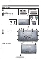
Remove the two screws. (ABA1379)
1
Remove the power button case.
2
Rear Case (509)
1
Power button case
Side input cover
POWER SW Assy
Power button case
Screw tightening order
Screw tightening order
Remove the two screws. (ABA1378)
3
Remove the two screws. (ABA1377)
4
Remove the side input cover.
The other screws are random order.
The other screws are random order.
5
Side input cover
Remove the two screws. (ABA1380)
6
Remove the two screws. (ABA1379)
7
Remove the 25 screws. (ABA1377)
8
Remove the rear case (509).
9
Rear case (509)
Rear case (509)
1
1
8
8
8
8
6
7
8
8
8
8
8
8
8
8
8
9
8
8
8
8
8
8
8
8
8
8
8
8
6
7
4
1
1
2
2
3
5
4
2
1
2
3
Screw tightening order
ABA1377
ABA1378
Reference
Summary of Contents for ARP3476
Page 10: ...10 PDP 5020FD 1 2 3 4 A B C D E F 1 2 3 4 2 2 SPECIFICATIONS ...
Page 11: ...11 PDP 5020FD 5 6 7 8 5 6 7 8 A B C D E F ...
Page 12: ...12 PDP 5020FD 1 2 3 4 A B C D E F 1 2 3 4 2 3 PANEL FACILITIES Front Section ...
Page 13: ...13 PDP 5020FD 5 6 7 8 5 6 7 8 A B C D E F Rear Section ...
Page 14: ...14 PDP 5020FD 1 2 3 4 A B C D E F 1 2 3 4 Remote Control Unit ...
Page 15: ...15 PDP 5020FD 5 6 7 8 5 6 7 8 A B C D E F ...
Page 21: ...21 PDP 5020FD 5 6 7 8 5 6 7 8 A B C D E F ...
Page 22: ...22 PDP 5020FD 1 2 3 4 A B C D E F 1 2 3 4 4 BLOCK DIAGRAM 4 1 OVERALL WIRING DIAGRAM 1 2 ...
Page 25: ...25 PDP 5020FD 5 6 7 8 5 6 7 8 A B C D E F OVERALL DIAGRAM PDP 5020FD ...
Page 31: ...31 PDP 5020FD 5 6 7 8 5 6 7 8 A B C D E F ...
Page 71: ...71 PDP 5020FD 5 6 7 8 5 6 7 8 A B C D E F ...
Page 192: ...192 PDP 5020FD 1 2 3 4 A B C D E F 1 2 3 4 9 6 PANEL CHASSIS SECTION ...


