162
PDP-5020FD
1
2
3
4
A
B
C
D
E
F
1
2
3
4
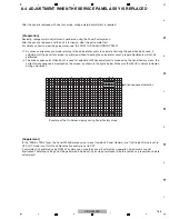
2. When manual adjustment is required after the DIGITAL Assy is replaced with one
for
service
If backup data cannot be transferred to the DIGITAL Assy because of defective parts, etc., after the DIGITAL Assy is replaced
and manual adjustment is performed, those manually adjusted data can be registered as adjusted data with the following
procedures. Once the data on the DIGITAL Assy are registered as adjusted data, the adjustment data for backup will be
automatically updated each time the unit is turned off. Therefore, if a DIGITAL Assy with adjusted data is mounted on the unit,
the following procedures are not required, even after manual adjustment.
PANEL INFORMATION
ETC. (+)
BACKUP DATA : NO OPRT
Key Down 7th
Key Down
SET
Right
SET (5 sec)
DIGITAL EEPROM : NO OPRT
DIGITAL EEPROM : REPAIR
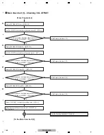
(1) Copying, using the Factory menu
1
Turn on the power.
2
Enter the Panel Factory mode.
3
Display the PANEL INFORMATION page, then check if "NO DATA!" is set for "DIG. EEP".
4
Register the changed adjustment data as adjusted data, as described for the following procedures, then transfer them as
backup
data.
(2) Copying, using the RS-232C commands
1
Turn on the power.
2
Issue the FAY command.
3
With the QS2 command, confirm that the main unit adjustment flag is "adjustment not completed."
4
Issue the FAJ command to register the changed adjustment data as adjusted data then transfer them as backup data.
5
With the QS2 command, confirm that the main unit adjustment flag becomes "adjustment completed."
6
Turn off the power.
5
Check if "ADJUSTED" is set for "DIG. EEP" on the PANEL INFORMATION page.
6
Turn off the power.
Summary of Contents for ARP3476
Page 10: ...10 PDP 5020FD 1 2 3 4 A B C D E F 1 2 3 4 2 2 SPECIFICATIONS ...
Page 11: ...11 PDP 5020FD 5 6 7 8 5 6 7 8 A B C D E F ...
Page 12: ...12 PDP 5020FD 1 2 3 4 A B C D E F 1 2 3 4 2 3 PANEL FACILITIES Front Section ...
Page 13: ...13 PDP 5020FD 5 6 7 8 5 6 7 8 A B C D E F Rear Section ...
Page 14: ...14 PDP 5020FD 1 2 3 4 A B C D E F 1 2 3 4 Remote Control Unit ...
Page 15: ...15 PDP 5020FD 5 6 7 8 5 6 7 8 A B C D E F ...
Page 21: ...21 PDP 5020FD 5 6 7 8 5 6 7 8 A B C D E F ...
Page 22: ...22 PDP 5020FD 1 2 3 4 A B C D E F 1 2 3 4 4 BLOCK DIAGRAM 4 1 OVERALL WIRING DIAGRAM 1 2 ...
Page 25: ...25 PDP 5020FD 5 6 7 8 5 6 7 8 A B C D E F OVERALL DIAGRAM PDP 5020FD ...
Page 31: ...31 PDP 5020FD 5 6 7 8 5 6 7 8 A B C D E F ...
Page 71: ...71 PDP 5020FD 5 6 7 8 5 6 7 8 A B C D E F ...
Page 192: ...192 PDP 5020FD 1 2 3 4 A B C D E F 1 2 3 4 9 6 PANEL CHASSIS SECTION ...

