AVH-P5150DVD/XN/RC
73
5
6
7
8
5
6
7
8
C
D
F
A
B
E
1
2
Fig.6
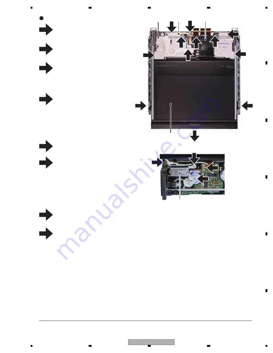
Remove the two screws and then remove
the two Guids(Right side, Left side).
Pull out the Monitor Assy in the direction
indicated by an arrow.
Remove the two screws and then remove
the Spring.
Remove the screw and then remove
the Arm and Cover.
Disconnect the connector.
Disconnect the connector.
Remove the three screws and then remove
the Motor Unit.
Removing the Motor Unit, the Drive Unit
can operate to lead to the Monitor Assy.
1
2
3
Removing the Monitor Unit 1/2 (Fig.6)
Monitor Assy
Motor Unit
Arm and Cover
3
Cover
1
Remove the five screws and then remove
the Cover.
Spring
4
4
4
4
4
4
5
6
7
8
5
6
6
6
7
7
8
Summary of Contents for AVH-P5150DVD
Page 21: ...AVH P5150DVD XN RC 21 5 6 7 8 5 6 7 8 C D F A B E ...
Page 60: ...AVH P5150DVD XN RC 60 1 2 3 4 1 2 3 4 C D F A B E ...
Page 61: ...AVH P5150DVD XN RC 61 5 6 7 8 5 6 7 8 C D F A B E ...
Page 114: ...AVH P5150DVD XN RC 114 1 2 3 4 1 2 3 4 C D F A B E 9 4 EXTERIOR 3 C C B A I C B A ...
Page 143: ...AVH P5150DVD XN RC 143 5 6 7 8 5 6 7 8 C D F A B E D b D a D a 1 2 D b1 2 CWW1763 ...
Page 147: ...AVH P5150DVD XN RC 147 5 6 7 8 5 6 7 8 C D F A B E ...
Page 165: ...AVH P5150DVD XN RC 165 5 6 7 8 5 6 7 8 C D F A B E L K J K SWITCH PCB UNIT L VOLUME PCB UNIT ...
Page 175: ...AVH P5150DVD XN RC 175 5 6 7 8 5 6 7 8 C D F A B E D SIDE A 0 50 60 70 80 90 A CN801 UNIT E ...
Page 176: ...AVH P5150DVD XN RC 176 1 2 3 4 1 2 3 4 C D F A B E D D DVD CORE UNIT 50 60 70 80 90 E ...


