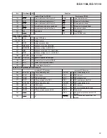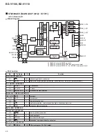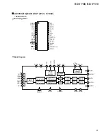
53
BD-V1100, BD-V1110
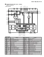
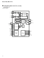
Control
Circuit
Command
Register
RY/BY
Buffer
RY/BY
Vcc
Vss
Vss
DQ0-DQ15
WE
BYTE
RESET
CE
OE
A-1
A0-A18
Erase
Circuit
Input/Output
Buffer
Data Latch
Y Decoder
Y Gate
STB
STB
8,388,608
Cell
Matrix
X Decoder
Address Latch
Chip Enable
and
Output Enable
Circuits
Writing
Circuit
Writing / Erase
Pulse Timer
Low-Vcc
Detection Circuit
2
23
13
32
43
33
44
12
14
31
3-11,
34-42
15-22,
24-31
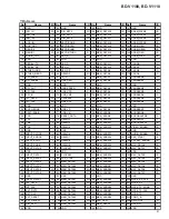
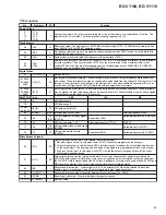
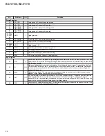
No.
Pin Name
Function
No.
Pin Name
Function
1
RY/BY
Redy/busy output
23
V
CC
Power supply (+5.0V
±
10% or
±
5%)
2
A
18
Address input
24
DQ
4
Data input/output
3
A
17
25
DQ
12
4
A
7
26
DQ
5
5
A
6
27
DQ
13
6
A
5
28
DQ
6
7
A
4
29
DQ
14
8
A
3
30
DQ
7
9
A
2
31
DQ
15
/A-
1
Data input/output, address input
10
A
1
32
V
SS
Ground
11
A
0
33
BYTE
8 bit or 16 bit switching
12
CE
Chip enable
34
A16
Address input
13
V
SS
Ground
35
A15
14
OE
Output enable
36
A14
15
DQ
0
Data input/output
37
A13
16
DQ
8
38
A12
17
DQ
1
39
A11
18
DQ
9
40
A10
19
DQ
2
41
A9
20
DQ
10
42
A8
21
DQ
3
43
WE
Write enable
22
DQ
11
44
RESET
Hard ware reset
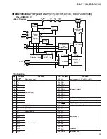
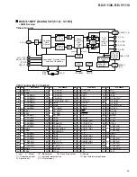
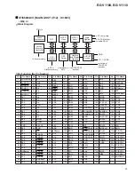
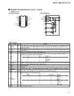
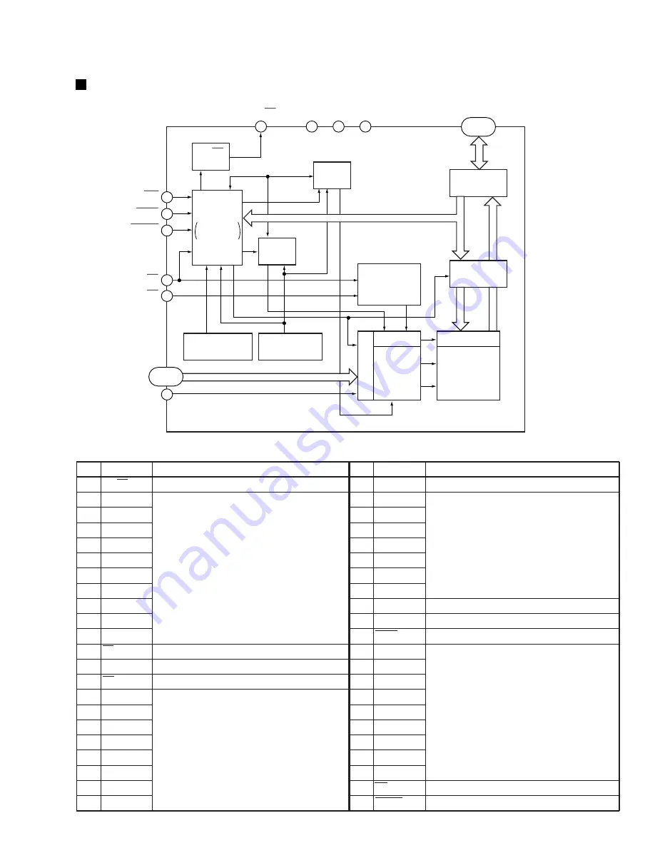
MBM29F800BA-70PF [MAIN ASSY (4/12) : IC1305, IC1306, IC1307 and IC1308]
• Flash ROM (8M) IC
•
Block Diagram
•
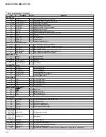
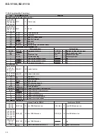
Pin Function


