46
BD-V1100, BD-V1110
Oscilloscope 3
Separator
DC Volt Meter
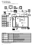
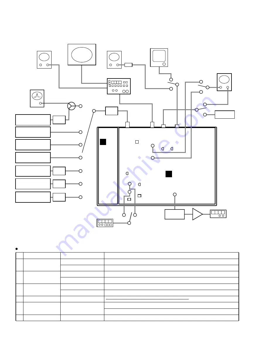
Fig.1 Adjustment Connections
S3
High Imp.
Probe
Frequency
Counter
Amp.
1
2
Oscilloscope 1
75
Ω
termination
through
Oscilloscope 2
Distortion Meter
Video Analyzer
Video
Audio
Output (L)
AUDIO
OUT
VIDEO
OUT
TO TV
CABLE IN
TV Receiver
TV Monitor
S2
S1
1
2
3
4
5
6
7
1
1
1
2
2
2
S5
S4
Spectrum Analyzer
ATT 2
ATT 3
ATT 4
ATT 5
QPSK Modulator
(105MHz)
EIA Color Bar CH
SINX/X CH
BTSC
Separation CH
QPSK Modulator
(70MHz)
256QAM Modulator
(663MHz)
64QAM Modulator
(513MHz)
ATT 1
TP1902
(VCO)
TP1901
(AGC)
TP1801
(BTSC R)
F2003
VR1901
VR1801 VR1701
TC1901
L1908
TP1802
(BTSC L)
TP1401
(54MHz VCXO)
MAIN ASSY
A
SWITCHING
POWER
SUPPLY
ASSY
E
T1901
1
QPSK Modulator
Center Freq. = 105MHz
All slots have to be opened. (for QPSK Tx Adj.)
2
EIA Color Bar
Video
EIA Color Bar 87.5% Mod.
Audio
1kHz Sin Wave
±
25kHz Dev.
3
SINX/X
Video
SINX/X (0.5MHz~3.75MHz)
Audio
400Hz Sin Wave
±
25kHz Dev.
4
BTSC Separation
Video
Black 0 IRE Flat Signal
Audio
L = 300Hz, R = 3.1kHz Sin Wave 14% Mod. Each CH
5
QPSK Modulator
Center Freq. = 70MHz
6
256QAM Modulator
Center Freq. = 663MHz
Video Stream = Full White APL100% MPEG2 Video
Audio Stream = 1kHz FS -20dB MPEG1 Audio
7
64QAM Modulator
Center Freq. = 513MHz
Data channel
Input Signals
Note 1 : Perform the NTSC ch setting if necessary.
2 : Set the Fv/Fa difference to -15dB.
6. ADJUSTMENT
Note : Refer to the "Service Know-how (SKB54005)" for the details.

