background image

14

BDP-170

1

2

3

4

A

B

C

D

E

F

1

2

3

4

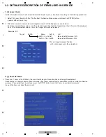
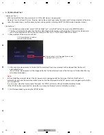
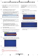
4.4  HOW TO WRITE BARCODE DATA USING A USB MEMORY DEVICE

• If the LOADER Assy is replaced, follow the procedure from 
  Step 1 below.
• If the MAIN BOARD Assy is replaced, follow the procedure 
  from Step 5 below.

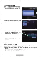
1.  Open Notepad from Accessories on your PC. 
 

Plug the USB memory device into the PC.

2.  Type the 64-digit barcode that is attached to the back of 
 

the LOADER Assy for service into a Notepad file.


(Be careful of input errors, because the barcode data are 


 adjustment data for the new part.)

3.  Store the Notepad file as "2D_barcode_data.txt " in the 
 

root directory of the USB memory device.


After storage, remove the USB memory device from the 

 PC.

4.  Plug the USB memory device in which the 
 

"2D_barcode_data.txt" file is stored into the BDP unit 


whose LOADER Assy has been replaced. 


(Make sure that the USB memory device is recognized.)

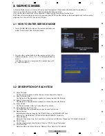
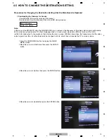
5.  Enter Service mode.
 

(See "HOW TO ENTER SERVICE MODE.")

6.  Select "[6] Repair Service" then press the [ENTER] button.

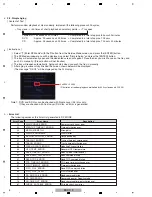
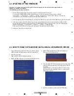
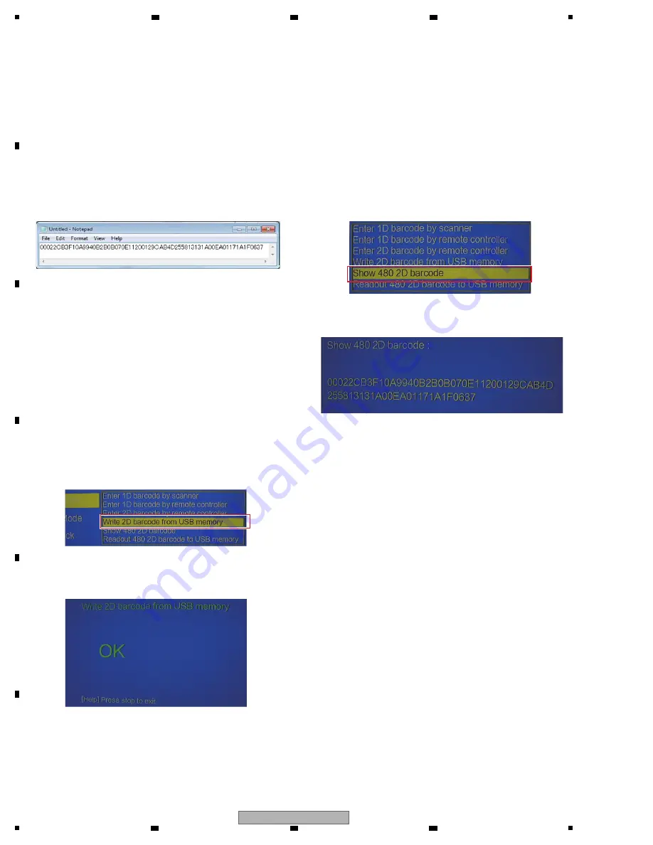
7.  Select "Write 2D barcode from USB memory" then press 
 

the [ENTER] button.

8.  The message "OK" will be displayed on the screen when 
 

copying of the barcode data from the USB memory device 

 is 

finished.

9.  Quit Service mode by pressing the [STOP] button.
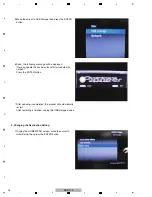
Note:

To prevent a future possible writing error, delete the 
"2D_barcode_data.txt" file from the USB memory device on 
the PC.

• If the MAIN BOARD Assy is replaced, the procedure is 
  completed at Step 9.
• If the LOADER Assy is replaced, continue the remaining 
  Steps below.

10.  Enter Service mode again.

11.  Select "[6] Repair Service" then press the [ENTER] 
 button.

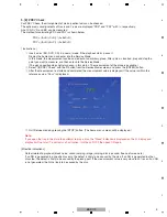
12.  Select "Show 480 2D barcode" then press the 
 [ENTER] 

button.

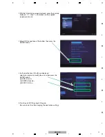
13.  Check that the 64-digit barcode being displayed is the 
 

same as that attached to the LOADER Assy. 


If the barcode is not the same, perform the procedure 


from Step 1 again.

Summary of Contents for BDP-170

Page 1: ...apan BDP 170 RRV4572 Blu ray 3DTM PLAYER BDP 170 BDP 80FD THIS MANUAL IS APPLICABLE TO THE FOLLOWING MODEL S AND TYPE S This service manual should be used together with the following manual s For SPECIFICATIONS and PANEL FACILITIES refer to the operating instructions Model Type Power Requirement DVD Region No BD Region No Serial No Remarks BDP 170 SXE AC 110 V to 240 V 5 C UR UR RUSSIA BDP 170 PWX...

Page 2: ... BDP170 SB0 08 BDP170 SB0 08 BDP170 SB0 P43 6 POWER BOARD ASSY 08 P015BE PW0 08 P015BE PW0 08 P015BE PW0 08 P015BE PW2 P43 17 CD Door ASSY 08 BDP150 DA1 08 BDP150 DA1 08 BDP150 DA1 08 BDL170 DA0 PACKING SECTION NSP P41 1 Software License Notice ARC8260 Not used Not used Not used P41 1 Software License Notice Not used 70 PONEER LCSB2 70 PONEER LCSB2 70 PONEER LCSB2 P41 2 Remote Control Unit RC 2426...

Page 3: ... and 08 BDP170 FV0 are constructed the same with the exception of some components including the following Note This list is not complete Only components that are available as service part are listed CF SWITCH BOARD ASSY Although 08 BDP160 SB0 and 08 BDP170 SB0 are different and are NOT COMPATIBLE Some components on these assy s are different Since these different components are not available as se...

Page 4: ... Wi Fi 4 pin cable is disconnected be sure to reconnect the cable so that the side on which the ferrite core is attached is connected to the MAIN BOARD Assy 3 When the Wi Fi 4 pin cable is to be replaced remove the ferrite core from the old cable then attach it to the new cable at a place approximately 30 mm away from the connector by wrapping the cable once around the ferrite core MAIN BOARD ASSY...

Page 5: ...reen If it does not appear slowly press the number keys with a 1 second interval 1 Enter FA mode For the former model and will not be used to exchange this Loader 2 Save FE log to USB For Design and Development purposes and cannot be used for Service 3 Save FA result to USB For Design and Development purposes and cannot be used for Service 4 Laser Check Verifies laser diode Refer to Laser Check fo...

Page 6: ...isplayed There are 17 items in the SP Mode the main items being for Production line and Design Development The following is to explain items usable in Service Other items require time for completion or are not suited for Service purposes If you select them by mistake press the STOP button to end that item you accidentally selected none of the items will affect the main unit 1 4 Laser Check Example...

Page 7: ...by the disc If an NG is generated in other discs too the defect is likely to be caused by the drive part However even if Pass is displayed after this test it is difficult to determine that the Driver is normal with these Pass judgments only Tray Close Foucus ON TOC Read Tray Open 1 cycle 15 seconds x 20000 completed in approx 83 hours 20 minutes Can be implemented on all of CD DVD and BD Cannot ch...

Page 8: ...be displayed on the FL display Note1 DVD and BD disc can be checked with Single Layer SL disc only If they are checked with Dual Layer DL disc an Error is generated The following serves as the Error List generated in SP MODE Error Code Error Name Description 12 PWR_CURVE_ERROR Power curve chk sum error 0x4E20 20000 Fifty times of random playback multiplied by 400 cycles equals 20 000 22 STARTUP_TI...

Page 9: ...rom the Service Mode screen and press the ENTER button 3 After the measurement is started and completed the measurement value is displayed If the value is within the reference value Pass is displayed 4 Quit Service mode by pressing the STOP button The home menu screen will be displayed Note If you open the tray in this state then attempt to play a disc the Close indication is displayed on the FL d...

Page 10: ...error rate will start 4 After error rate measurement is finished for the outermost track measurement will be stopped then the tray will automatically open For a DL disc measurement will be stopped after that for the outermost track of the first layer is finished then the tray will automatically open Note In Error Rate Measurement mode if the AC power cord is unplugged with the tray open the Error ...

Page 11: ...values across discs or BD players used the results measured using the GGV1368 will not be completely the same Use these values just for reference For error rate measurement of an entire DL disc including that of the second layer it is recommended to measure the error rate using a PC When a PC is used for measurement measured error rate values will be graphed which makes this method suitable for er...

Page 12: ...place the LOADER Assy Mechanical point Write barcode data for pickup adjustment Electric point When replace the LOADER Assy This time 2 When replace the MAIN BOARD Assy Mechanical point Read out barcode data for pickup adjustment Before replacing MAIN BOARD Assy Write barcode data for pickup adjustment After replacing MAIN BOARD Assy Electric point When replace the MAIN BOARD Assy About barcode da...

Page 13: ...ase insert the USB memory device into unit While the screen shows the information that a USB memory device has been inserted please press HOME MENU button to enter the menu then find USB devices through Home Menu Initial Setup Options Update USB Storage After press the ENTER button the system will search the update file itself to update 4 After reset the unit is available for test 1 Plug a USB mem...

Page 14: ...has been replaced Make sure that the USB memory device is recognized 5 Enter Service mode See HOW TO ENTER SERVICE MODE 6 Select 6 Repair Service then press the ENTER button 7 Select Write 2D barcode from USB memory then press the ENTER button 8 The message OK will be displayed on the screen when copying of the barcode data from the USB memory device is finished 9 Quit Service mode by pressing the...

Page 15: ... Initial Setup then press the ENTER button 3 Move the cursor to Options then press the ENTER button Note In the case of the BDP 80FD after the MAIN BOARD Assy is replaced the frequency of the video output signals will become 50 Hz which may disable some TVs from displaying videos In such a case play back a BD disc for use in the U S A with 60 Hz video output stop playback then display the menu scr...

Page 16: ...ayed Here an update file has been found Start update with version Press the ENTER button 7 After updating is completed the product will automatically restart After restarting is finished unplug the USB storage device 2 Changing the Destination Setting 1 Display the HOME MENU screen move the cursor to Initial Setup then press the ENTER button ...

Page 17: ...supplied remote control unit 3 Select 9 Change Area at the bottom then press the ENTER button 4 As the destinations 0 to 8 are displayed select your region by moving the cursor then press the ENTER button 4 SXE Russia 5 PWXE Oceania 8 CUXE U S A 5 Turn the unit OFF then back ON again Be sure to do this after changing the destination setting ...

Page 18: ...nation change has been successfully finished Tip It is recommended to confirm the region code at the same time 4 Press the HOME MENU button to return to the HOME MENU screen 4 Writing the Latest Firmware to the Product 1 Download the latest firmware for the product from the Website specially for service engineers to a USB storage device 2 Perform updating in the same manner as that described in 1 ...

Reviews: