93
C-AX10
4
5
4
×
2
2
×
2
2
3
6
10
12
11
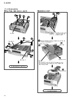
Note:
Slide the PC Board to rear slide (2 or 3 cm away) after
removing screws, connectors, Heat Sink ASSY and Rear Panel.
And PC Board can lift to upper side when matches a projection
part of the Side Wall with a cut part of the PC Board.
Unhook
Unhook
CRAD ASSY
Remove the Shield Plate B where is in the bottom of
CRAD ASSY. (Three screws)
1
Remove the DIGITAL I/O ASSY, DSP ASSY
and Main Shield.
Heat Sink Assy
Side Wall
Remove a CN101 from the
Power Cord.
Remove all screws.
Power Cord
Remove four connectors.
Note:
Do not remove a screw
of the SG ASSY.
FRAD ASSY
CN405
Front
side
CN406
CN407
CN301
FRAD ASSY
×
3
7
9
8
Caution: Perform styling so that each wire does not come near.
Pass a wire through a slit of
the shield plate every one set
(three sets).
Note:
It becomes an equal interval
wires of each group.
Front side
CN1803
Bind in upper side of CN1803.
Keep distance with wire of
CN1803 and FFC away and
bind it.
DSP ASSY
FFC
CN2109
J2102
Bind
Bind
Bind two pairs of wires
in the player.
DIGITAL
I/O ASSY
Clamp the wires to
connect the DIGITAL
I/O ASSY
Styling in installation (DSP ASSY)
Clamp two wires
(Gray and Black).
Power Cord
G
F
E
Summary of Contents for C-AX10
Page 9: ...9 C AX10 ...
Page 13: ...C AX10 13 A B C D 1 2 3 4 1 2 3 4 E FRAD ASSY F CRAD ASSY 24 576MHz 24 576MHz 3 1 3 A D BLOCK ...
Page 14: ...C AX10 14 A B C D 1 2 3 4 1 2 3 4 H AUDIO A ASSY 3 1 4 D A BLOCK AUDIO A ASSY ...
Page 15: ...C AX10 15 A B C D 1 2 3 4 1 2 3 4 I AUDIO B ASSY 3 1 5 D A BLOCK AUDIO B ASSY ...
Page 16: ...C AX10 16 A B C D 1 2 3 4 1 2 3 4 A DIGITAL I O ASSY B DSP ASSY 3 1 6 DIGITAL SIGNAL BLOCK ...
Page 17: ...C AX10 17 A B C D 5 6 7 8 5 6 7 8 to D A SECTION Hi bit Hi bit Hi bit ...
Page 18: ...C AX10 18 A B C D 1 2 3 4 1 2 3 4 A E F Hi bit Hi bit Hi bit FRONT 3 1 7 µ COM PORT BLOCK ...
Page 35: ...C AX10 35 A B C D 5 6 7 8 5 6 7 8 AUDIO SIGNAL ROUTE 9 3 3V 3 3V x2 1 10W 3 6 G ...
Page 37: ...C AX10 37 A B C D 5 6 7 8 5 6 7 8 AUDIO SIGNAL ROUTE G1 6 11 11 4 6 G ...
Page 39: ...C AX10 39 A B C D 5 6 7 8 5 6 7 8 G1 6 5 6 G ...
Page 66: ...C AX10 66 A B C D 1 2 3 4 1 2 3 4 AUDIO A ASSY H SIDE B Q910 Q912 Q908 Q902 Q901 Q907 Q903 H ...
Page 67: ...C AX10 67 A B C D 5 6 7 8 5 6 7 8 Q901 Q905 Q906 Q904 907 Q903 ANP7291 D H ...
Page 71: ...C AX10 71 A B C D 5 6 7 8 5 6 7 8 Q1003 Q1007 Q1001 Q1005 Q1006 Q1004 Q1009 ANP7291 D I ...

