background image


CD-MR70/UC

3

5

6

7

8

5

6

7

8

C

D

F

A

B

E


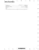
SPECIFICATIONS

Power source  ..................................................................14.4 V DC (10.8 — 15.1 V allowable)
Grounding system  ................................................................................................ Negative type
Max. current consumption  ............................................................................................ 200 mA
Dimensions ...................................................................................... 102 (W) 

67 (H) 

46 (D)

Weight ............................................................................................................................ 0.12 Kg

Note:

• Specifications and the design are subject to possible modification without notice due to improvements.

Summary of Contents for CD-MR70/UC

Page 1: ... 90801 1760 U S A PIONEER EUROPE NV Haven 1087 Keetberglaan 1 9120 Melsele Belgium PIONEER ELECTRONICS ASIACENTRE PTE LTD 253 Alexandra Road 04 01 Singapore 159936 PIONEER CORPORATION 2004 CD MR70 UC CRT3268 WIRED MARINE REMOTE CONTROL CD MR70 UC For details refer to Important symbols for good services K ZZA APR 2004 printed in Japan ...

Page 2: ...eaning should be made securely When you find the procedures bearing any of the symbols be sure to fulfill them 2 Adjustments To keep the original performances of the product optimum adjustments or specification confirmation is indispensable In accordance with the procedures or instructions described in this manual adjustments should be performed 3 Cleaning For optical pickups tape deck heads lense...

Page 3: ... Power source 14 4 V DC 10 8 15 1 V allowable Grounding system Negative type Max current consumption 200 mA Dimensions 102 W 67 H 46 D Weight 0 12 Kg Note Specifications and the design are subject to possible modification without notice due to improvements ...

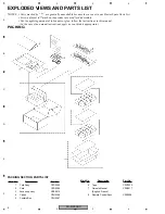
Page 4: ...the product are used for disassembly For the applying amount of lobricants or glue follow the instructions in this manual In the case of no amount instructions apply as you think it appropriate Mark No Description Part No 1 Cord Assy CZD5385 2 Cord CZD5386 3 Accessory Assy CZE5014 4 Carton CZH5366 5 Contain Box CZH5367 6 Tape CZN7023 7 Owner s Manual CZR5017 English French 8 Remote Control Assy CZ...

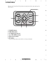
Page 5: ...oneer Head Unit and remote control unit with the same name have the same function 1 VOLUME buttons 2 BAND ESC button 3 5 5 DISC P Ch buttons 4 2 3 TRK SEEK buttons 5 SRC source button 6 ATT button Volume is decreased about one tenth the set volume Attenuator 1 2 5 6 4 3 ...

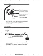
Page 6: ...n plug extension cable supplied Red Connect to the electric terminal controlled by the boat s ignition switch 12 V DC ON OFF When connecting use the power extension cable supplied Black ground Connect to the boat s ground lead System Connections Connect the wired remote input of a Pioneer Head Unit and the remote control pin plug When connecting to the remote control pin plug s wired remote input ...

Reviews: