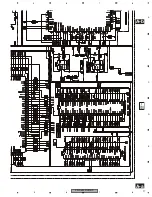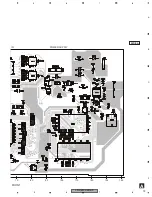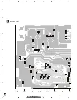
CD-UB100/XN/UC
18
1
2
3
4
1
2
3
4
C
D
F
A
B
E
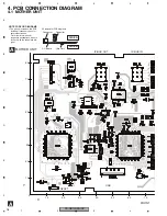
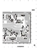
4. PCB CONNECTION DIAGRAM
4.1 MOTHER UNIT
A
A
MOTHER UNIT
NOTE FOR PCB DIAGRAMS
1.The parts mounted on this PCB
include all necessary parts for
several destination.
For further information for
respective destinations, be sure
to check with the schematic dia-
gram.
Capacitor
Connector
P.C.Board
Chip Part
SIDE B
SIDE A
2.Viewpoint of PCB diagrams
10
20
30
40
50
60
70
10
20
30
40
50
60
70
80
0
X
Y
FRONT
IP-BUS OUT
RESET
USB
IP-BUS IN
Summary of Contents for CD-UB100
Page 5: ...CD UB100 XN UC 5 5 6 7 8 5 6 7 8 C D F A B E 1 SPECIFICATIONS ...
Page 14: ...CD UB100 XN UC 14 1 2 3 4 1 2 3 4 C D F A B E A a A b A b 1 1 8 mH A MOTHER UNIT ...
Page 17: ...CD UB100 XN UC 17 5 6 7 8 5 6 7 8 C D F A B E A a A b A b A a 220 0R0 R632 47K ...
Page 36: ...CD UB100 XN UC 36 1 2 3 4 1 2 3 4 C D F A B E 8 OPERATIONS ...
Page 37: ...www mobiteh com ...

