CDJ-100S
45
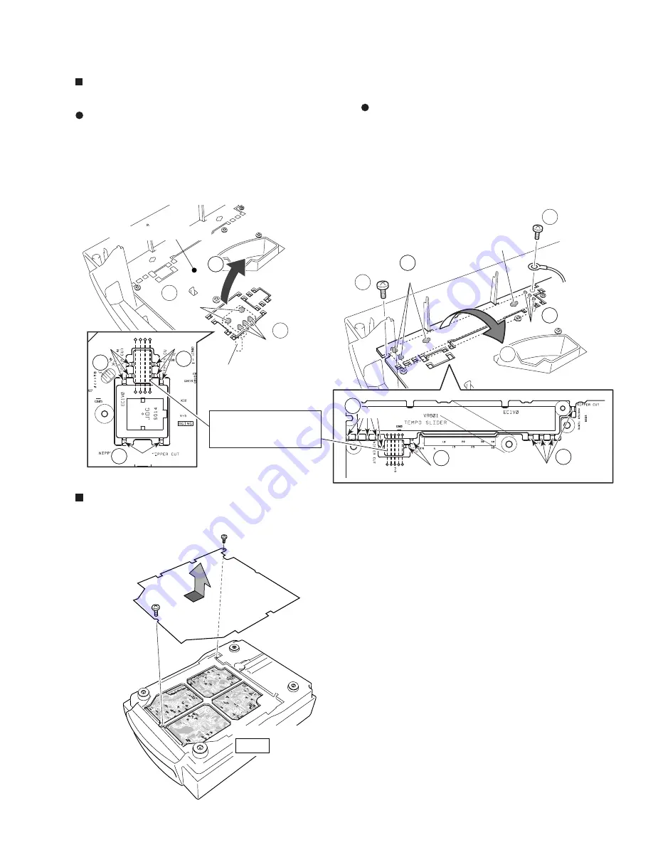
Bottom Plate
MOTHER BOARD ASSY
SIDE B
Screw
G
Screw
G
2
2
4
2
Solder
Solder
Screw
A
2
Screw
A
Cut
Rotary Encoder
DISPLAY BOARD ASSY
3
2
2
2
Solder
Solder
Solder
3
3
3
3
3
Pay attention to solder crack
for the jumper wires, short-
circuits, etc.
Cut
Cut
Cut
Cut
Cut
Measuring Points (TP) for Diagnosis
Remove the two screws
G
at the bottom plate. Then measuring at
the each points becomes possible.
Exchange Methods for Rotary Encoder (S614: DSX1051) and
Slide Volume (VR601: DCV1009)
Rotary Encoder (S614: DSX1051)
1
Remove the jog dial, the nut (M9) and the jog washer at the top of
the unit. (Refer to "Removal of the DISPLAY BOARD Assy".)
2
Unsolder the rotary encoder and cut the 8 locations shown in the
figure with nippers or similar.
3
Raise the P.C. board while paying attention to the jumper wires
and remove the rotary encoder.
Slide Volume (VR601: DCV1009)
1
Remove the slide knob from the top of the unit. (Refer to
"Removal of the DISPLAY BOARD Assy".)
2
Remove the two screws
A
.
3
Unsolder the slide volume and cut the 11 locations shown
in the figure with nippers or similar.
4
Raise the circuit board while paying attention to the jumper
wires and remove the slide volume.


