CDJ-800MK2
112
1
2
3
4
1
2
3
4
C
D
F
A
B
E
6
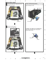
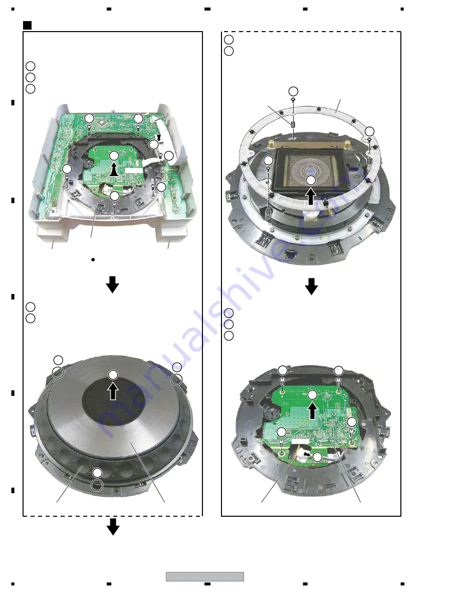
Remove the three screws.
7
Remove the SW ring.
8
Disconnect the connector.
9
Remove the four screws.
10
10
Remove the JFLB Assy.
JOG A
JFLB Assy
JOGB Assy
JOG B
SW ring
SW spring 25
5
7
6
6
6
Caution:
Be careful not to lost SW spring 25.
1
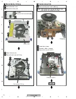
Disconnect the flexible cable.
2
Remove the six screws.
3
Remove the JOG section.
4
Unhook the three hooks.
5
Remove the JOG A and JOG Bs.
JOG Section
5
JOG section
Spacer
Spacer
1
Bottom view
CN600
CN1601
3
2
2
2
2
4
9
9
9
8
9
2
2
4
4
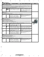
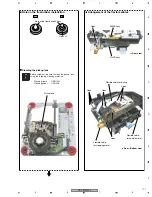
Note:
To work on the unit having it set upside-down, place
spacers below it, as shown in the photo below, to avoid
imparting stress to the sheet SW of the JOG section.
Summary of Contents for CDJ-800MK2
Page 27: ...CDJ 800MK2 27 5 6 7 8 5 6 7 8 C D F A B E MODE MODE 3 3 A 27 24 26 19 36 ...
Page 29: ...CDJ 800MK2 29 5 6 7 8 5 6 7 8 C D F A B E Data PANEL DATA Digital A 2 3 3 3 A 3 3 A 23 ...
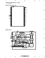
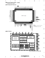
Page 130: ...CDJ 800MK2 130 1 2 3 4 1 2 3 4 C D F A B E Pin Function ...
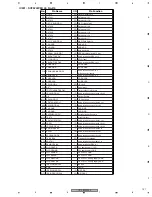
Page 135: ...CDJ 800MK2 135 5 6 7 8 5 6 7 8 C D F A B E Pin Function ...
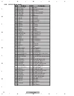
Page 139: ...CDJ 800MK2 139 5 6 7 8 5 6 7 8 C D F A B E Pin Function ...
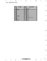
Page 143: ...CDJ 800MK2 143 5 6 7 8 5 6 7 8 C D F A B E ...
Page 153: ...CDJ 800 7 5 6 7 8 5 6 7 8 C D F A B E ...


