CDJ-800MK2
125
5
6
7
8
5
6
7
8
C
D
F
A
B
E
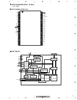
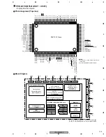
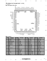
P1_0
P1_1
P1_2
P1_3
P1_4
P1_5/INT3
P1_6/INT4
P1_7
P2_0
P2_1
P2_2
P2_3
P2_4
P2_5
P2_6
P2_7
VSS
P3_0
VCC2
P3_1
P3_2
P3_3
P3_4
P3_5
P3_6
P3_7
P4_0
P4_1
P4_2
P4_3
P9_6/ANEX1
P9_5/ANEX0
P9_4
P9_3
P9_2/TB2IN
P9_1/TB1IN
P9_1/TB0IN
BYTE
CNVSS
P9_7/XCin
P8_6/XCOUT
RESET
XOUT
VSS
XIN
VCC1
P8_5/NM1
P8_4/INT2
P8_3/INT1
P8_2/INT0
P8_1
P8_0
P7_7
P7_6
P7_5/T
A2IN
P7_4/T
A2OUT
P7_3/CTS2/R
TS2/T
A1IN
P7_2/CLK2/T
A1OUT
P7_1/RXD2/SCL2/T
A0IN (Note 1)
P7_0/TXD2/SD
A2/T
A0OUT (Note 1)
P4_4
P4_5
P4_6
P4_7
P5_0
P5_1
P5_2
P5_3
P5_4
P5_5
P5_6
P5_7/CLKOUT
P6_0/CTSWRTS0
P6_1/CLK0
P6_2/RXD0/SCL0
P6_3/TXD0/SDA0
P6_4/CST1/RTS1/CTS0/CLKS1
P6_5/CLK1
P6_6/RXD1/SCL1
P6_7/TXD1/SDA1
P0_7/AN0_7
P0_6/AN0_6
P0_5/AN0_5
P0_49AN0_4
P0_3/AN0_3
P0_2/AN0_2
P0_1/AN0_1
P0_0/AN0_0
P10_7/AN7/KI3
P10_6/AN6/KI2
P10_5/AN5/KI1
P10_4/AN4/KI0
P10_3/AN3
P10_2/AN2
P10_1/AN1
AVSS
P10_0/AN0
VREF
AVCC
P9_7/ADTRG
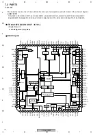
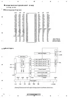
M16C/30P Group
8
Port P0
8
Port P1
Internal peripheral functions
Timer (16-bit)
Output (timer A): 3
Input (timer B): 3
A/D converter
(10 bits x 18 channels)
System clock
generation circuit
XIN-XOUT
XCIN-XCOUT
Memory
ROM
(Note 1)
SB
R0H
R1H
R0L
R1L
R2
R3
A0
A1
FB
USP
ISP
INTB
PC
FLG
RAM
(Note 2)
Multiplier
M16C/60 series16-bit CPU core
UART or
clock synchronous serial I/O
(3 channels)
CRC arithmetic circuit (CCITT)
(Polynomial : X
16
+X
12
+X
5
+1)
Watchdog timer
(15 bits)
DMAC
(2 channels)
8
Port P2
8
Port P3
8
Port P4
8
Port P5
8
Port P6
8
Po
rt
P7
8
Po
rt
P8
8
Po
rt
P8_5
8
Po
rt
P9
8
Po
rt
P10
(Note 1) ROM size depends on microcomputer type.
(Note 2) RAM size depends on microcomputer type.
• Display Microcomputer
Block Diagram
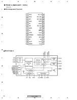
PEG237B (DFLB ASSY : IC501)
Pin Arrangement (Top view)
NOTES:
1. P7_0 and P7_1 are N channel open-drain
output pins.
2. Use the M16C/30P on VCC1=VCC2.
1
2
3
4
5
6
7
8
9
10
11
12
13
14
15
16
17
18
19
20
21
22
23
24
25
26
27
28
29
30
80
79
78
77
76
75
74
73
72
71
70
69
68
67
66
65
64
63
62
61
60
59
58
57
56
55
54
53
52
51
100
99
98
97
96
95
94
93
92
91
90
89
88
87
86
85
84
83
82
81
32
31
33
34
35
36
37
38
39
40
41
42
43
44
45
46
47
48
49
50
Summary of Contents for CDJ-800MK2
Page 27: ...CDJ 800MK2 27 5 6 7 8 5 6 7 8 C D F A B E MODE MODE 3 3 A 27 24 26 19 36 ...
Page 29: ...CDJ 800MK2 29 5 6 7 8 5 6 7 8 C D F A B E Data PANEL DATA Digital A 2 3 3 3 A 3 3 A 23 ...
Page 130: ...CDJ 800MK2 130 1 2 3 4 1 2 3 4 C D F A B E Pin Function ...
Page 135: ...CDJ 800MK2 135 5 6 7 8 5 6 7 8 C D F A B E Pin Function ...
Page 139: ...CDJ 800MK2 139 5 6 7 8 5 6 7 8 C D F A B E Pin Function ...
Page 143: ...CDJ 800MK2 143 5 6 7 8 5 6 7 8 C D F A B E ...
Page 153: ...CDJ 800 7 5 6 7 8 5 6 7 8 C D F A B E ...

