CDJ-800MK2
126
1
2
3
4
1
2
3
4
C
D
F
A
B
E
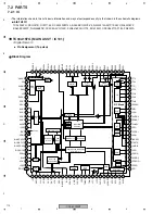
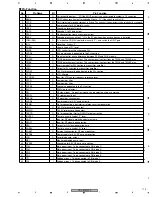
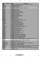
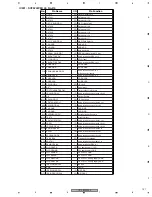
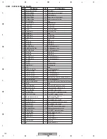
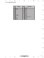
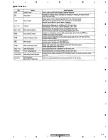
Pin Function
No.
Pin Name
I/O
Pin Function
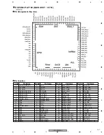
1
–
I
Not used (ground)
2
TCH/REL
I
Volume input (A/D conversion port) For VINYL SPEED ADJUST
3
MODEL2
I
Model setting 2 Distinguish between CDJ-800MK2, CDJ-1000MK3 and DVJ-1000.
4
MODEL1
I
Model setting 1
5
–
O
Not used (non connection)
6
JOG1
I
Pulse period measurement processing
7
–
O
Not used (non connection)
8
–
−
Not used (ground)
9
CNVss
−
For built-in flash memory updating (not used)
10 –
I
Not used (ground)
11 –
I
Not used (ground)
12 XRST
−
Reset input
13 XOUT
−
16 MHz clock input
14 Vss
−
Ground
15 XIN
−
16MHz clock input
16 Vcc
−
Power supply 5 V
17 XNMI
I
18 –
I
Not used (power supply 5 V)
19 –
I
Not used (power supply 5 V)
20 –
I
Not used (power supply 5 V)
21 –
I
Not used (power supply 5 V)
22 –
I
Not used (power supply 5 V)
23 –
I
Not used (power supply 5 V)
24 –
I
Not used (power supply 5 V)
25 JOG2
I
Two-phase pulse signal input Input signal of a TA2OUT terminal is a period of "H", up count (clockwise) at
rising edge of TA2IN terminal and down count (counterclockwise) at falling edge.
26 JOG1
I
27 TOUCH
I
JOG touch sensor
28 JSCLK
O
Serial clock signal for JOG-FL
29 –
O
Not used (non connection)
30 J_SDO
O
Communication Serial data signal for JOG-FL
31 FLSDO
O
Communication Serial data signal for DATA-FL
32 –
I
Not used (non connection) For built-in flash memory updating
33 FLSCLK
O
Communication Serial clock signal for DATA-FL
34 –
I
Not used (non connection) For built-in flash memory updating
35 SDO
O
Communication Data out signal for MPU (MAIN ASSY)
36 SDI
I
Communication Data in signal for MPU (MAIN ASSY)
37 CLK
O
Communication Clock signal for MPU (MAIN ASSY)
38 XCS
O
Communication Chip select signal for MPU (MAIN ASSY)
39 –
O
Not used (non connection)
40 –
O
Not used (non connection)
41 –
I
Not used (pull up)
42 FLLAT
O
Communication Latch signal for DATA-FL
43 FLBK
O
Communication Blank signal for DATA-FL
44 JXSTB
O
Communication Latch signal for JOG-FL
45 JBK
O
Communication Blank signal for JOG-FL
46 XCE
I
Not used (pull up)
47 LED24
O
LED control for RELOOP/EXIT button 0 : Lights-out
48 LED23
O
LED control for REALTIME CUE OUT button 0 : Lights-out
49 LED22
O
LED control for PLAY/PAUSE button 0 : Lights-out
50 LED21
O
LED control for CUE button 0 : Lights-out
Summary of Contents for CDJ-800MK2
Page 27: ...CDJ 800MK2 27 5 6 7 8 5 6 7 8 C D F A B E MODE MODE 3 3 A 27 24 26 19 36 ...
Page 29: ...CDJ 800MK2 29 5 6 7 8 5 6 7 8 C D F A B E Data PANEL DATA Digital A 2 3 3 3 A 3 3 A 23 ...
Page 130: ...CDJ 800MK2 130 1 2 3 4 1 2 3 4 C D F A B E Pin Function ...
Page 135: ...CDJ 800MK2 135 5 6 7 8 5 6 7 8 C D F A B E Pin Function ...
Page 139: ...CDJ 800MK2 139 5 6 7 8 5 6 7 8 C D F A B E Pin Function ...
Page 143: ...CDJ 800MK2 143 5 6 7 8 5 6 7 8 C D F A B E ...
Page 153: ...CDJ 800 7 5 6 7 8 5 6 7 8 C D F A B E ...


