CDJ-800
62
1
2
3
4
1
2
3
4
C
D
F
A
B
E
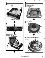
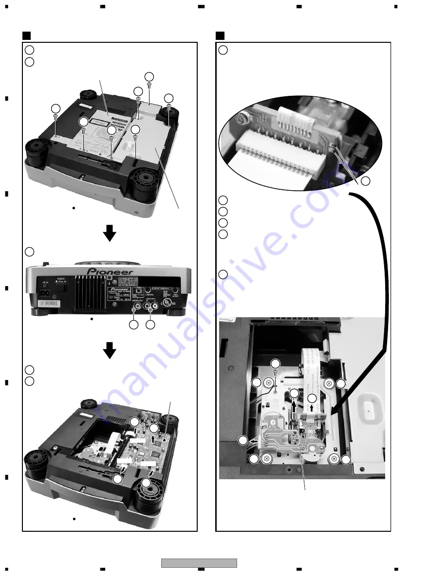
7.1.3 DISASSEMBLY
1
Remove three screws to remove the Bottom Plate M.
2
Remove four screws to remove the Bottom Plate P.
1
Remove three screws to remove the Bottom Plate M.
2
Remove a screw.
3
Remove four screws.
4
Disconnect a spindle connector.
5
Disconnect a pickup flexible cable
[Caution in the Mechanism Assy replacement]
•
When removing the Mechanism Assy, short-circuit a LD
Short land
5
before disconnecting a flexible cable from
the connector.
6
Remove the CD Mechanism.
•
When installing the Mechanism Assy, release the short
-circuit of LD Short land
5
after connecting the flexible
cable to the connector. (For LD fracture prevention)
3
Remove two screws.
4
Disconnect two flexible cables and a connector.
5
Remove the MAIN Assy.
MAIN Assy
1
CD Mechanism
2
Bottom Plate M
Bottom Plate P
MAIN Assy
CD Mechanism
CN113
CN111
CN122
2
2
2
2
1
1
1
3
2
3
3
3
3
4
5
Bottom View
Bottom View
Rear View
3
4
4
4
5
6
5
Short land
Summary of Contents for CDJ-800MK2
Page 27: ...CDJ 800MK2 27 5 6 7 8 5 6 7 8 C D F A B E MODE MODE 3 3 A 27 24 26 19 36 ...
Page 29: ...CDJ 800MK2 29 5 6 7 8 5 6 7 8 C D F A B E Data PANEL DATA Digital A 2 3 3 3 A 3 3 A 23 ...
Page 130: ...CDJ 800MK2 130 1 2 3 4 1 2 3 4 C D F A B E Pin Function ...
Page 135: ...CDJ 800MK2 135 5 6 7 8 5 6 7 8 C D F A B E Pin Function ...
Page 139: ...CDJ 800MK2 139 5 6 7 8 5 6 7 8 C D F A B E Pin Function ...
Page 143: ...CDJ 800MK2 143 5 6 7 8 5 6 7 8 C D F A B E ...
Page 153: ...CDJ 800 7 5 6 7 8 5 6 7 8 C D F A B E ...


