CDJ-800MK2
85
5
6
7
8
5
6
7
8
C
D
F
A
B
E
6. ADJUSTMENT
1. Service Mode Summary
This unit is controlled with two microcomputers. One microcomputer performs the button input and indication of FL and LED
(display section), and the other microcomputer drives the player (player section).
Test mode is prepared in each microcomputer.
1
Confirmation mode of the button of display section and display function
It is the mode which confirms button input and display function.
2
The mode which confirms the operation of the player section (use the remote control unit)
Connect the remote control unit (RU-V101) to the data copy terminal of the player, and confirms the operation.
3
Version confirmation mode
Can confirm software version of each microcomputer.
2. Confirmation Mode of the Button of Display Sectiont and Display Function
Enter this mode when turns the power on while pressing the [MEMORY] key and [TIME] key simultaneously.
It can light display part in this mode partially as follows. And it can perform each button and the input of volume and indication
normally. Further, display lights while pressing the button.
Button
Display
LED
QUICK RETURN
Light LED of QUICK RETURN
AUTO BEAT (1, 2, 4, 8)
Light LED of each beat
REVERSE
Light LED of REVERSE
CUE
Light LED of CUE
PLAY/PAUSE
Light LED of PLAY/PAUSE
LOOP IN
Light LED of LOOP IN
LOOP OUT
Light LED of LOOP OUT
JOG MODE
Light LED of VINYL
TEMPO RANGE
Light LED of TEMPO RANGE
MASTER TEMPO
Light LED of MASTER TE M PO
FL
TRACK/SEARCH - FWD
Light "REMAIN", "M", " : ", "88" of a minute and "8" of high-order digit of a second
TRACK/SEARCH - REV
Light "88" of the track number, "A. COU" and "QUICK RETURN"
SEARCH - FWD
Light "S", "F", "8" of low order digit of a second and "88" of a frame
SEARCH -REV
Light all of Playing bar and frame
TIME MODE/AUTO CUE
Light "+1888%" of tempo, "888" of BPM, "WIDE", "MT" and "BPM"
RELOOP/EXIT
Light all FLs, JOG-FLs and LEDs of the main unit
CALL
Light all the rotation display parts of JOG-FL
MEMORY
Light all CUE point marks of JOG-FL
EJECT
Light "VINYL" character and a frame (blue) of the JOG-FL center
JOG ADJUST VOLUME
Goes out the ring A of JOG-FL when the volume position is less than the center. And
light it when it is more than the center.
SLIDER VOLUME
Goes out the ring B of JOG-FL when the volume position is less than the center. And
light it when it is more than the center.
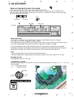
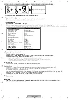
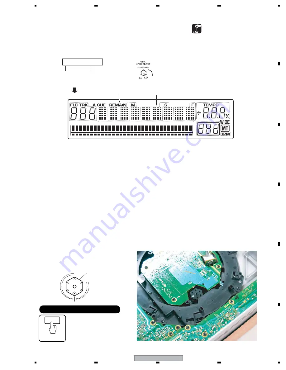
• Mode for checking the load on the Jog dial
It is the mode which judges the load (light/-- heavy) numerically when rotating JOG dial.
If it goes into the above-mentioned check mode of button and display function of the display part, a TOUCH/RELEASE knob is
made in the maximum (right-hand side) and arbitrary buttons are pushed once, it will become JOG load check mode and top speed
and time will displayed on a dot-matrix part.
Measuring method
In this state, if you rotate the Jog dial rapidly either clockwise or counterclockwise, figures are displayed.
For example, if "16.14 0135" is displayed, it means as follows:
16.14: Highest speed (given that the normal [1x] speed is when it takes 1.8 sec for the Jog dial to rotate one full turn.)
0135: Time (msec) required for the Jog dial to decrease its speed from 3x speed to 1.5x speed
As to the time required for the Jog dial to decrease its speed, if the measurement is performed for several times
repeatedly, from the second measurement and afterward, the average of the current required time and the previous
required time is displayed. Thus, after several measurements, the result becomes closer to the mean.
Notes
• Perform the measurement of load on the Jog dial more than three times.
• The measurement result is displayed only when the Jog dial is rotated 7 times normal speed "07.00" or more.
Management value
Jog management value: 150
±
25 (msec)
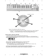
Load adjustment method
Remove the screw fixing the adjust plate, then screw it into the hole corresponding to the value (-1, -2, -3, +1, or +2) for a
load to be added:
-1, -2, -3 : To decrease the load
+1, +2
: To increase the load
FL display
-1
-2
-3
+2
+1
0
To increase
the load
To decrease
the load
0.0: 0m
0.0: 0m
Time (msec)
Adjust plate
JOG Check Mode : CANCEL
POWER OFF
Time (msec)
Max speed
Max speed
Summary of Contents for CDJ-800MK2
Page 27: ...CDJ 800MK2 27 5 6 7 8 5 6 7 8 C D F A B E MODE MODE 3 3 A 27 24 26 19 36 ...
Page 29: ...CDJ 800MK2 29 5 6 7 8 5 6 7 8 C D F A B E Data PANEL DATA Digital A 2 3 3 3 A 3 3 A 23 ...
Page 130: ...CDJ 800MK2 130 1 2 3 4 1 2 3 4 C D F A B E Pin Function ...
Page 135: ...CDJ 800MK2 135 5 6 7 8 5 6 7 8 C D F A B E Pin Function ...
Page 139: ...CDJ 800MK2 139 5 6 7 8 5 6 7 8 C D F A B E Pin Function ...
Page 143: ...CDJ 800MK2 143 5 6 7 8 5 6 7 8 C D F A B E ...
Page 153: ...CDJ 800 7 5 6 7 8 5 6 7 8 C D F A B E ...

