10
CX-890
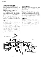
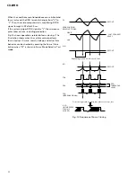
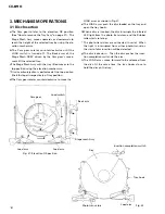
b) Brake circuit
Servo withdrawal will deteriorate during setting and
track jump. Thus, the system uses the brake circuit to
provide stable withdrawal to servo loop.
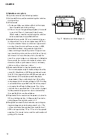
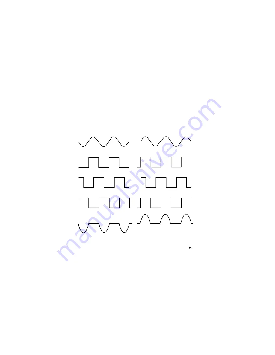
The brake circuit detects the direction of lens move-
ment, and outputs only drive signal in the opposite
direction from the lens movement. Thus, the system
delays the speed of the lens movement to stabilize
withdrawal of the tracking servo.
The system judges sliding direction of track from TEC
and MIRR signals, as well as the relationship of their
phase.
TEC
TZC
(TEC "SQUARED UP" )
(INTERNAL SIGNAL )
MIRR
MIRR LATCHED AT
TZC EDGES
=
SWITCHING PULSE
EQUALIZER OUTPUT
(SWITCHED)
DRIVE DIRECTION
Note: In the illustration, the phase of equalizer output is shown as the same as with that of TEC.
FORWARD
LENS MOVING FORWARDS
(INNER TRACK TO OUTER)
LENS MOVING BACKWARDS
Time
REVERSE
Fig. 14 Tracking Brake Circuit
Summary of Contents for CDX-MG6056ZH
Page 5: ...4 CDX MG6346ZH MG6446ZH 2 2 EXTERIOR ...
Page 7: ...6 CDX MG6346ZH MG6446ZH 2 3 CD MECHANISM ...
Page 14: ...13 CDX MG6346ZH MG6446ZH 5 6 7 8 5 6 7 8 D C B A A A b A EXTENSION UNIT ...
Page 15: ...14 CDX MG6346ZH MG6446ZH 1 2 3 4 1 2 3 4 D C B A 1 A a A b D CD CORE UNIT STS UNIT A a ...
Page 16: ...15 CDX MG6346ZH MG6446ZH 5 6 7 8 5 6 7 8 D C B A A a A b B 2 B KEYBOARD UNIT A a ...
Page 17: ...16 CDX MG6346ZH MG6446ZH 1 2 3 4 1 2 3 4 D C B A A a A b 1 A EXTENSION UNIT A b ...
Page 18: ...17 CDX MG6346ZH MG6446ZH 5 6 7 8 5 6 7 8 D C B A A a A b 2 A b ...
Page 28: ...27 CDX MG6346ZH MG6446ZH 1 2 3 4 1 2 3 4 D C B A CN701 CN901 EXTENSION UNIT SIDE B A A B D ...
Page 30: ...29 CDX MG6346ZH MG6446ZH 1 2 3 4 1 2 3 4 D C B A SIDE B KEYBOARD UNIT B B ...
Page 32: ...31 CDX MG6346ZH MG6446ZH 1 2 3 4 1 2 3 4 D C B A CD CORE UNIT SERVO UNIT SIDE B C C ...
Page 34: ...33 CDX MG6346ZH MG6446ZH 1 2 3 4 1 2 3 4 D C B A CD CORE UNIT STS UNIT SIDE B D D ...
Page 36: ...M M4 CARRIAGE 1 12 D CN301 35 CDX MG6346ZH MG6446ZH 5 6 7 8 5 6 7 8 D C B A E C ...
Page 38: ...1 41 G CN801 37 CDX MG6346ZH MG6446ZH 1 2 3 4 1 2 3 4 D C B A MOTOR PCB A F SIDE B F D ...


