background image

Summary of Contents for CJ-V55

Page 1: ... 4 SCHEMATIC DIAGRAMS AND P C BOARDS PATTERN 32 5 BLOCK DIAGRAM 82 6 ELECTRICAL PARTS LIST 84 7 ADJUSTMENTS 91 8 1C DESCRIPTION 102 9 NOTES ON REPLACING THE LITHIUM CELL AND RAM IC3 TC5564APL 15 105 PIONEER ELECTRONIC CORPORATION 4 1 Meguro 1 Chome Meguro ku Tokyo 153 Japan PIONEER ELECTRONICS SERVICE INC P O Box 1760 Long Beach California 90801 U S A PIONEER ELECTRONICS OF CANADA INC 505 Cochrane...

Page 2: ...29 2 or equivalent between the earth ground and all exposed metal parts of the appliance input output terminals screwheads metal overlays control shaft etc Plug the AC line cord of the appliance directly into a 1 20V AC 60Hz outlet and turn the AC power switch on Any current measured must not exceed 0 5mA ANY MEASUREMENTS NOT WITHIN THE LIMITS OUTLINED ABOVE ARE INDICATIVE OF A PO TENTIAL SHOCK HA...

Page 3: ......

Page 4: ......

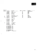
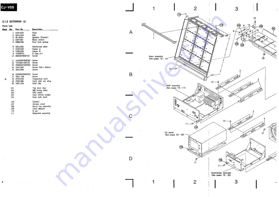
Page 5: ...BZ30P060FMC Screw 11 AMZ40P080FMC Screw 12 TNC35P140FZK Screw 13 PMH20P100FMC Screw 14 DBA1007 Screw 3 5 x 12mm 15 SBA1068 Screw 16 PMB5QP300FMC Screw 17 SBA 194 Screw A 18 DDE1034 Connection cord 19 PDE1065 Cord with pin plug 20 DEC1184 Shell clip A 101 Top door stay 102 MB fixing plate 103 DRS guide 104 Door switch holder 105 Door lock shaft 106 Cabinet 107 Airway cover 108 Earth lug assembly 10...

Page 6: ......

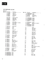
Page 7: ...B1207 Channel 18 DBH1035 CA spring 19 YE30FUC E ring 0 3 20 BPZ30P080FCU Screw 21 PMB40P080FMC Screw 22 AMZ40P080FMC Screw 23 SNC1078 Protection net Mark No Part No 102 103 104 106 107 108 109 110 111 112 113 114 115 116 117 118 119 120 121 122 123 124 126 127 128 129 Description LAMP Stay A Glow lamp CA holder A Hinge holder Rear plate Cord damper Coin guide A Coin guide cover Insertion guide A C...

Page 8: ......

Page 9: ...ate 14 DEC1220 Bushing 116 Cord damper 15 DXB 108 Bearing 117 Triangle frame L 16 DBH1107 Tension spring under 118 Triangle frame S 17 DMS1012 Synchro belt 119 CNTB 18 DNK1622 Center pulley 120 Motor holder 19 DNK1623 Synchro pulley 121 Sensor holder 20 DBH1108 Adjustment spring 122 Motor pulley 21 DEC 176 Plastic rivet 22 VBN 002 Speed nut 23 DNK1632 Menu cap U 24 DNK1628 Menu 25 DLA1300 Worm gea...

Page 10: ......

Page 11: ......

Page 12: ......

Page 13: ...ll Electromagnetic counter Push button Remote control unit 6 BBZ30F080FZK Screw 7 BBZ30P060FMC Screw 8 PMB30P050FCU Screw 101 CNNB 102 CRJB 104 DIPS 105 RMJB 106 107 108 109 110 Front panel B Terminal holder Counter holder P C B holder Side frame L 111 112 113 114 Side frame R Reinforced frame Rear panel B Connector assembly A B ...

Page 14: ......

Page 15: ......

Page 16: ......

Page 17: ...tic rivet Cord clamper Coller SP holder Plate B Spring A 16 DDG1026 17 DEB1106 18 DLA1337 19 DEB1123 20 BBZ30P080FMC AC power cord Air damper Lock shaft Rubber washer Screw 21 PMZ30F040FMC Screw IPZ30P060FMC Screw AMZ30P060FMC Screw PMZ30P060FMC SCrew 25 PDZ30P050FMC Screw 26 BBZ40P080FMC Screw 27 AMZ40P250FMC Screw 28 DDD1027 17P flexible cord Mark No Part No 101 102 103 104 105 106 107 108 109 1...

Page 18: ...in gear Clamper holder T 41 PBP 009 42 PNW1448 43 DLA1286 44 PEB1014 45 DEC 176 46 BPZ20P080FZK 47 BPZ30P100PMC Screw 48 BSZ26P040FMC Screw 49 FMZ20P030FMC Screw 50 PMZ20P080FMC Screw Steel ball j 3 Clamper Roller Floating rubber Plastic rivet Screw Mark _No Part No Description_ 51 BMZ26P120FMC Screw 52 PCZ30P050FZK Screw 53 DBA1023 Link screw 54 PBA1002 Floating screw 55 PBA 125 Screw 56 WT26D047...

Page 19: ......

Page 20: ...YX104M25 Semlconductive ceramic capacitor 2 PBH1008 Drive spring 3 PLA1004 Guide bar 4 PNW1063 Carriage plate PXM1O02 Motor 6 PWY1009 Pickup assembly 7 PMZ20P030FMC Screw 8 DXX1361 Spindle motor assembly 9 PYY1025 Motor assembly 101 Motor pulley 102 Carriage M board 29 3 PACKING ...

Page 21: ...MC Screw 7 DHG1164 Case 8 DRW1156 Label B 9 DRB1027 Operating instructions English 10 DHC1015 Reinforcement plate 101 Packing sheet 102 Vinyl bag 103 Vinyl bag 104 Cord clamper 105 Caution label F pad R pad Packing case Connection cord Connection cord with pin plug 106 107 Follow card bag Follow up card SIDE VIEW ...

Page 22: ...ing be sure to use parts of identical designation marked capacitors and resistors have parts numbers This is the basic schematic diagram but the actual circuit may vary due to improvements in design 5 SCcH iIhe underlined indicates the switch position MAIN SECTION CD SECTION OUTSIDE OF P C BOARDS DOOR SW i wr r u DUAnuo DOWN LIMIT TRAY SW KtYB CLAMP SW S301 1 IN SIDE SW S302i2 EKEY S303 3 S301 A S...

Page 23: ......

Page 24: ......

Page 25: ...4 1 MAIN SECTION 4 1 1 OVERALL CONNECTION DIAGRAM ...

Page 26: ......

Page 27: ...M mm CNNB VALIDATOR A LITHIUM COUNTER CNNB 1CN1011 CNNB ICN1 13 C0NT DWG1138 ...

Page 28: ... SfrQ YOI leornoi I 03j anno laornoi anno sole anno anno ir rrnoi jjia ROTAQIJAV Rarnuoo TH03 anno irornol anno ler mol i xmc P C B connection diagram is viewed from the foil side 88 r rowa Tnoo LO ScV anno lar mol FBRO ...

Page 29: ...rqMAj A 3 a 8 s r 33V L0 J33A Ql IA I IIDA aW3q RMAJ I A A a ...

Page 30: ...u Q m 4 1 3 LAMP PSWB ACIN AND ASEL A LAMP1 cA d CD o o o o D ...

Page 31: ... 5 0601 RCG 009 0 01 AC400V At fa DTT1039 POWER TRANSFORMER T DTH111 N31 AC IN A A A_ K022 A L5 Aijp2il Lr 0502 _ csoifTrT_ aci2 v AC120V 60f DDG1025 1YEL A LAMP2 RJ 4P55 TO POWB CN77 GRN P55 _ TO POWB CN76 f GRN _ fCN75 fa TO POWB AL i CN76 I blu f P55 DSXIOIO A 43435 AC OUTLET DKN 108 ...

Page 32: ......

Page 33: ...St0ppj m m POWB POWB ICN23I ICN121 PREB DWK1 Oil LOJB AUDIO PLAYER3 PLAYERg PLAYER I CDJB PAMP ICN44I PAMP CN251 3 ...

Page 34: ...awoa awoa This P C B connection diagram is viewed from the foil side r ror wa a3Fia aioj IfGYAjq Sfl3YAJS ES3YA W 8LQ0 aMAS 8MAS ...

Page 35: ...aMAa aawoa fiaMHCHSHAaT jjia HOTAQIJAV 3MA3 laSPiol awoa a r aaaa sfRol O5omwa awoa This P C B connection diagram is viewed from the foil side aawoa J33A FEMFIOaSHAFIT 8YM01 f anno 8TP131 aaaa feTnol ...

Page 36: ......

Page 37: ......

Page 38: ...1 2 3 4 5 6 4 1 6 PAMP SPTB AND NETWORK ASSEMBLY H P50 to PREB CN24 P50 4 P55 B P56 D B D LI STH1100 L3 STH1021 L4 STH 327 Brl SSG 004 1 ...

Page 39: ...NETWORK ASSEMBLY SWN1197 ...

Page 40: ...esv uo awoa fYSROI YOOrHWQ SMAS inection diagram is viewed from the foil side flB iA3S8 flOWT3M H3300W H3300W aiM HTDM3J aiM HTDH3 3012 R3XA3R2 R3T33WT Ye r ri iw2 yjaMassA fiowt3h asm rsAPiol ...

Page 41: ...38 ATOfl anA 8TM0 2809 883M 9810 WAfla aY3 l 31 IMO Y r A TMOO TMOO TMOO ...

Page 42: ...S CNTB AND ROTA CONT CONT CONT ICN1141 ICN1081 ICN 1041 DOOR SWITCH PQWB POWB 0 0 ICN1 20l ICN341 KEYB DWS1 101 N o lei ies lei Sj ip f j f 5 CONT CONT CONT CONT ICN 1021 ICNTToI ICN1121 ICN 1001 DISP DWG 1 129 MESS DWG 1128 m r _1_I 4 ...

Page 43: ...Q10 1NVETER TC6 1 2 t FORCUS DRIVE I IC2 SERVO CONTROL ...

Page 44: ......

Page 45: ......

Page 46: ......

Page 47: ...MJSW ...

Page 48: ...PLUNGER1 A REJECT ...

Page 49: ... y r r rxwa 0JMA eoso ...

Page 50: ...9 I 5 I 8 T33J32 3210 flOTOM W3LM ...

Page 51: ...NOTE The encircled numbers denote measuring points i Wave Forms schematic diagram TP2 2 Pin PLAY MODE 2V div 200 p sec div IC3 76 Pin STOP MODE 2V drv 200nsec div ...

Page 52: ...rr r r rrr ...

Page 53: ...re are J 5 and K 560 3 56x1C 47k 3 47 x 10 0 5 Q 0R5 1 Q 010 Ex 2 When there are 5 62k 3 562 x Miscellaneous Ps Mark Symbol Desc MESS DISP KEYS BRAN ROTA POSS LAMP CNTB PAMP SPTB LOJB PREB POWB ACIN ASEL FSWB CONT OPER CRJB RMJB CDJB DIPS CNNB Network assent C702 C704 C701 C703 A FU1 F A FU2 FU4 F A FU5 F A FU601 F Micro switc A Power tran A AC Power Electromagr 32 ...

Page 54: ...R H 6 I HF Miscellaneous Parts Mark Symbol DescriDti MESS Part No DWG1128 Mark A Symbol Description AC outlet Part No DKN 108 DISP DWG1129 A Ballast DTH1114 KEYB DWS1101 Channel DXB1107 BRAN A Lithium cell DEM1001 ROTA A Strain relief VEC 201 POSS Motor Menu DXM1033 LAMP Motor assembly Menu DXX1368 CNTB Remote control unit DXR1O07 PAMP DWH1007 A Connection cord DDE1034 SPTB A Fluorescent lamp sock...

Page 55: ...Description Part No Mark Symbol Description Part No C801 RESISTOR Mark Symbol Description R801 CKPUYF223Z25 _ Part No RD1 6PM121J Q401 Q403 Q404 Q402 D401 D402 UN4112 UN4212 2SB1185 2SD1762 1SR139 400 CAPACITORS Mark Symbol Description Part No LOJB C401 0403 C402 CEAL470M6R3 CEAS101M25 CKPUYF223Z25 SEMICONDUCTORS Mark Symbol Description Part No RESISTORS Mark Symbol Description Part No Q50 Q51 CAP...

Page 56: ...cription Part No RY1 Relay RSR1014 VR1 Volume 20k DCS1013 VR2 VR3 Volume 100k DCS1014 COILS Mark Symbol Description Part No Other resistors RD1 6PMCODJ L1 L2 AF choke coil DTH1116 ACIN CAPACITORS Mark Symbol Description Part No COIL C13 C14 33 100 DCH1018 Mark Symbol Description Part No C7 100 100 DCH1019 A L301 Line filter VTL 004 C6 10 100 DCH1022 cacn CEASR22M50 CAPACITORS C18 CEAS010M50 Mark S...

Page 57: ... 009 018 019 CEAS010M50 L1 L2 LAU010K 010 011 CEAS102M35 F1 F20 3 Terminal filter VTH1001 006 CEAS221M25 CAPACITORS 003 CEAS4R7M50 Mark Symbol Description Part No 004 016 017 CEAS470M25 001 007 008 CKCYF103Z50 C58 Capacitor array DCG1004 2200p X 8 RESISTORS 01 02 CCCCH150J50 Mark Symbol Description Part No C42 C43 C44 CCCCH470J5Q CEAS010M50 A R116 DCN1002 R114 R115 RS1LMF103J C4 C7 C30 C33 C35 C38...

Page 58: ...tion Part No COILS Mark Symbol Description 4P mini DIN socket VKN1072 Part No LI 3 3mH STH1100 RMJB L3 3 9mH STH1021 L4 0 22mH STH 327 SEMICONDUCTORS CAPACITORS Mark Symbol Description Part No Mark Symbol Description Part No D4 01 D404 MTZJ5 6B Cl CES4220KJ C2 CES4100KJ CAPACITOR C4 CES4DX1R8KJ Mark Symbol Description Part No RESISTOR C401 CKCYF103ZS0 Mark Symbol Description Part No RESISTORS Mark...

Page 59: ...DWX1117 DEGT MJSW HRMB REJC DWX1U6 A T201 Power transformer DTT1037 A FU201 Fuse 315mA REK 075 Slide switch DSH1011 DOWN LIMIT TRAY Lever switch CLAMP DSK1001 Slide switch INSIDE PSHI003 Pickup assembly PWY1009 A AC power cord DDG1026 Hour meter VCX 006 Select motor assembly DXX1358 Motor SLIDER DISC LOAD PXM1002 DISC SELECT Motor assembly PYY1025 Spindle motor assembly DXX1361 Semiconductive cera...

Page 60: ...MA333J50 C204 CEAS222M16 C34 C51 C66 CQMA472J50 C221 C226 CEAS330M16 RESISTORS C206 CEAS471M10 CEAS472M16 Mark Symbol Description Part No C227 CKCYF103Z50 VR8 Semi fixed lk VRTB6VS102 C207 C208 CQMA102J50 VR2 Semi fixed 10k VRTB6VS103 VR3 VR7 Semi fixed 22k VRTB6VS223 C213 C214 CQMA471J50 Other resistors RD1 6PMCTCJ C215 C216 CQMA472J50 C217 C218 CQMA683J50 OTHERS C211 C212 CQMA821J50 Mark Svmboi ...

Page 61: ...rew when the menu stops directing its surfaces to the front Fig 7 4 6 Finally turn the menu and check that the menu stops directing all of its three surfaces to the front at every 120 rotation Fig 7 1 Fig 7 2 Fig 7 3 7 1 MECHANICAL ADJUSTMENTS 7 1 1 MAIN SECTION Three sides of the menu synchronous adjustment Fig 7 1 I PREPARATIONS Adjust without installing the motor menu Fix center pulley to menu ...

Page 62: ...EP II DISC RETURN key When the operation is completed check that the gap between the top of the rotation lever and the upper side of the sixth tray in the magazine is 0 3 2 If the distance is not within the specified range turn screw to adjust the position of the sensor plate and press the lOkeys again in the sequence of f 83 STILL STEP DISC SELECT key STILL STEP DISC RETURN key until the distance...

Page 63: ...isc YEDS 7 4 Tracking balance adjustment filter 5 Loop gain adjustment filter 6 Signal generator 7 Frequency counter 8 Other general tools 9 Remote control unit RU V101 Service Mode The CD main unit can be operated independently when remote control unit RU V101 is connected to the unit For the operation refer to Service manual 1 ARP1912 Service Mode page 14 Note Before operating the remote control...

Page 64: ...oscilloscope to pin 1 RF RF output of TP1 and measure the P P voltage of RF waveform Adjust VR1 Laser power so that the value is within 1 5Vp p j v 3 LD LASER DIODE OUTPUT POWER CONFIRMATION Confirmation less than 0 13mW Set to Service mode Press 1 MULTI SPEED M kev fOl and turn ON LD laser diode Place sensor of the laser power meter immediately above the object lens and confirm that the output po...

Page 65: ...rt a 4kHz cutoff low pass filter Fig 7 8 Pin 2 TRK ERR 0 5V div 5msec div TP1 Pin 2 TRK ERR Grating Null point Turn the screwdriver and find null point Photo 7 1 Maximum Then turn slowly the screwdriver counterclockwise amplitude from the null point and adjust at the point where the waveform Tracking error signal firstly becomes maximum amplitude See Photo 7 2 Note If the screwdriver is pressed st...

Page 66: ...r of the disc by pressing i MULTI SPEED key Press l MULTI SPEED 1 key H and 1 MULTI SPEED 1 kev l2l to start turning the disc Observe pin 2 TRK ERR Tracking error of TP1 with an oscilloscope and adjust with VR5 TRK BAL Tracking balance volume so that the DC component of the tracking error disappears Note Before proceeding with the above adjustments be sure to adjust the tracking error offset B i i...

Page 67: ...d adjust with the tangential screw so that the eye pattern becomes clear Fig 7 9 and 7 10 The adjusting point is the middle point between the point where the eye pattern becomes deteriorate by turning the tangential screw clockwise and the point where the eye pattern becomes deteriorate by turning the tangential screw counterclockwise As a criterion observe that the overall waveform is clear and o...

Page 68: ...Photo 7 7 Unsatisfactory Optimum adjustment Unsatisfactory ...

Page 69: ...t 1 2kHz 20mV div 5mV div CHI X CH2 Y Probe 10 1 X axis TP1 Pin 5 FCS IN Y axis TP1 Pin 6 FCS ERR VR3 FCS GAN lVp p Note Depending upon oscillators some of them output DC when their power turned ON Therefore it is desirable to connect oscillator after turning the power ON Phase Adjust with VR3 FCS GAN Focus gain volume so difference 90 that the lissajous figure of the oscilloscope becomes horizont...

Page 70: ...2kHz 2Vp p Note Depending upon oscillators some of them output DC when their power turned ON Therefore it is desirable to connect oscillator 50mV div 5mV div CHI X CH2 Y Probe 10 1 X axis TP1 Pin 3 TRK IN Y axis TP1 Pin 2 TRK ERR VR4 TRK GAN after turning the power ON Phase Adjust with VR4 TRK GAN Tracking gain volume difference 90 so that the lissajous figure of the oscilloscope becomes horizonta...

Page 71: ...wdriver etc Fig 7 6 Connect frequency counter which is measurable over 10MHz to pin 8 of TP2 PLCK Adjust with VR8 VCO ADJ VCO adjustment volume so that the value of frequency counter becomes 4 275 0 01MHz 11 METHOD TO CONFIRM S CHARACTER FOCUS ERROR TP1 Pin 6 PCS ERR Set to Service mode Short circuit between pin 5 FCS IN Focus in of TP1 and GND Press 1 MULTI SPEED 1 kev m and observe the waveform ...

Page 72: ...drive output Buzzer drive output Money received signal from the coin acceptor Normal 1 Money received 0 for about 45 through 50msec Asynchronous serial Baud rate 4800bps Data bit 8bit Stop bit Ibit Command transmission to the CD player Asynchronous serial Baud rate 4800bps Data bit 8bit Stop bit lbit Status reception from the CD player Pulse signal input for control the menu board rotation Normal ...

Page 73: ......

Page 74: ...IP switch 45 cs 12 PCI 46 A0 I Address bus for access the RAM and microcomputer 13 PC2 47 A1 14 PC3 48 A2 15 PC4 49 SL1 0 Selection control signal of CDP audio input 16 PC5 50 SL0 17 PC6 51 Non connection IF PD7 52 FULL nr Bill validator signal Not used 19 Non connection 53 CANCEL SW i Cancel key input from the wired remote control IF SEG dp 0 Segment drive signal of the 7 seg LED FT SEG g FF DEP ...

Page 75: ...o ON 2 While simultaneously pressing four keys the volume and keys and the cancel A and B keys on the remote control unit set the power switch to ON A buzzer sounds in a few seconds indicating that the clear operation is completed Note An error may occur if you set the power switch to OFF while pressing these four keys When the data is cleared the rate settings return to their default values 3 tun...

Page 76: ......

Page 77: ...E MODE 14 PIONEER ELECTRONIC CORPORATION 4 1 Meguro 1 Chome Meguro ku Tokyo 153 Japan PIONEER ELECTRONICS SERVICE INC P O Box 1760 Long Beach California 90801 U S A PIONEER ELECTRONICS OF CANADA INC 505 Cochrane Drive Markham Ontario L3R 8E3 Canada PIONEER ELECTRONIC EUROPE N V Keetberglaan 1 2740 Beveren Belgium PIONEEH ELECTRONICS AUSTRALIA PTY LTD 178 184 Boundary Road Braeside Victoria 3195 Au...

Page 78: ...ical and mechanical parts in the appli ance have special safety related characteristics These are often not evident from visual inspection nor the protection afforded by them necessarily can be ob tained by using replacement components rated for vol tage wattage etc Replacement parts which have these special safety characteristics are identified in this Service Manual Electrical components having ...

Page 79: ...CJ V55 2 PARTS LOCATIONS 2 1 EXTERIOR Signboard upper Top door panel upper DAH1379 DNK1610 Key sheet B DAH1383 ...

Page 80: ......

Page 81: ......

Page 82: ...2 3 COMMANDER SECTION FRONT VIEW REAR VIEW DIN socket Connector VKN1072 assembly iv Remote control DXR1007 ...

Page 83: ......

Page 84: ...E MENU BOARD Illumination sheet DEC1224 A Fluorescent lamp socket upper DKK1006 Coin return cover DNK1616 Coin return boor DNK1618 Grill board SMA2291 Note As to the construction of these parts refer to the exploded view Caster A DXB1022 ...

Page 85: ...g DBH1102 Servo mechanism assembly REJC DAC1196 Synchro gear DNS1080 Timing pulley DNK1578 A Fuse FU201 315mA REK 075 Timing belt DMS1011 Front panel DNB1012 bpring XT DBH1105 1 Air damper DEB1106 A Power transformer DTT1037 A AC power cord DDG1026 Microcomputer PD0068 ...

Page 86: ...OOR ASSEMBLY 1 Open the menu door and remove six screws 2 Loosen four screws and remove two screws and two R pins to remove the menu board assembly to remove the upper lamp assembly 3 Remove two screws to remove the CA holder B assembly Fig 3 4 ...

Page 87: ...lley in the direction of arrow Note When the synchro belt is replaced be sure to perform the three sides of the menu synchronous adjustment Menu board assembly Synchro pulley 3 4 REMOVING THE LAMP AND NETWORK ASSEMBLY 1 Remove six screws D to remove the network assembly 2 Remove four screws to remove the LAMP 3 5 REMOVING THE ROTA AND POSS 1 Remove four screws D to remove the ROTA 2 Remove a screw...

Page 88: ...r screws to remove the DI 4 Remove eifto screws to remove to KEYB 3 8 REMOVING THE SPEAKER WOOFER 1 Remove four scmws end disconnect to connector 3 7 REMOVING THE AMP COMMANDER AND CD PLAYER 1 Remove three screws to remove the AMP c 2 to remove the commander 2 Remove two screws to remov 3 Remove two screws to remove the CD playe 12 ...

Page 89: ... BOARD LOJB LINE OUT JACK BOARD PREB PRE AMPLIFIER BOARD POWB POWER BOARD ACIN AC INPUT BOARD ASEL AMPLIFIER VOLTAGE SELECTOR BOARD PSWB POWER SWITCH BOARD CDJB CD JACK BOARD CONT CONTROL OPER OPERATION DIPS DIP SWITCH CRJB CD REMOTE JACK BOARD RMJB REMOTE CONTROL JACK BOARD CNNB CONNECTION BOARD CD PLAYER SECTION EKEY EJECT KEY DEGT DIGITAL DECOADING UNIT ANLG ANALOG UNIT DJAK DIGITAL JACK PJAK P...

Page 90: ... set 2 TIME Time set 2 CHAPTER Track set 1 SEARCH Search lOkey Numerical input DISPLAY FUNC 1 no entry STILL FUNC 2 no entry C MODE FUNC 3 no entry VIDEO FUNC 4 no entry 1 STOP M FUNC 5 Stop marker 1 START FUNC 6 Start AUDIO FUNC 7 no entry SPEED FUNC 8 no entry 1 OPEN FUNC 9 Magazine eject 1 Normal function command 2 Function command is different from the LD V530 Not marked No entry command Play ...

Page 91: ...R OTHER OUTLET UNLESS THE BLADES CAN BE FULLY INSERTED TO PREVENT BLADE EXPOSURE ATTENTION POUR PREVENIR LES CHOCS ELECTRIOUES NE PAS UTILISER CETTE FICHE POLARISEE AVEC UN PROLONGATEUR UNE PRISE DE COURANT OU UNE AUTRE SORTIE DE COURANT SAUF Si LES LAMES PEUVENT ETRE INSEREES A FOND SANS EN LAISSER AUCUNE PARTIE A DECOUVERT i CONTENTS CAUTIONS ON INSTALLATION 4 CARE OF DISCS 4 PREPARATION HOW TO ...

Page 92: ......

Page 93: ...s enoncfees dans le Reglement sur les perturbations radioelectriques section appareil numerique du Ministere des Communications Handle the power cord by the plug Do not pull out the plug by tugging the cord and never touch the power cord when your hands are wet as this could cause a short circuit or electric shock Do not place the unit a piece of furniture etc on the power cord or pinch the cord N...

Page 94: ... sheet matches the discs The external speaker phase is properly set and the right and left speakers are positioned properly With this unit use discs which display the mark shown below nCOMPACT km DIGITAL AUDIO When holding discs do not touch their signal surfaces Hold the edges or one edge and the center hole Do not affix labels or adhesive tape to the label surfaces Also do not scratch or damage ...

Page 95: ...f the main unit door is held to the main unit with a magnet To open it pull the upper part towards you A string is attached as stopper on the left side To remove the main unit door for connection etc hold the door up and pull the two projections located on the bottom of the door out of the slit When working on the inside of the main unit put the removed main unit door beside the right side of the ...

Page 96: ...und terminal CONNECTING THE EXTERNAL SPEAKERS External speakers can be connected to the EXTERNAL SPEAKERS terminals located on the rear of the main unit Connect the terminals on this unit to the terminals on the speakers and the terminals on the unit to the Loosen cap Insert wire Tighten cap NOTE Do not allow any of the cord s conductors to protrude from the terminals or touch any other conductors...

Page 97: ......

Page 98: ...BY A QUALIFIED SERVICE PERSON AND SHOULD CONFIRM TO ALL LOCAL CODES To prevent coin input install the supplied stopper in the the coin slot ATTACHING THE BILL ACCEPTOR When using bills for the CD jukebox the bill acceptor must be installed CAUTION THIS INSTALLATION SHOULD BE MADE BY A QUALIFIED SERVICE PERSON AND SHOULD CONFIRM TO ALL LOCAL CODES Open the cover of the money storage located on the ...

Page 99: ...onnect the connection cord 12 Reinstall the coin box i Attach the bill acceptor to the bill holder insert jt jnt0 the s ot with the labeled side facing out ii Fasten the bill holder with the two screws iii Close the menu door Use an NB 2JA 400 made by CONLUX USA for the bill acceptor DRA1107 ...

Page 100: ...S TO THE MAGAZINES Insert any discs which you may have into the magazine Up to six Position discs with the label side downward discs may be inserted The numbering of the discs begins with 1 at the topmost tray and then increases in order from 2 to 6 for ID DRA1107 ...

Page 101: ...agazine if no discs are required CAUTIONS REGARDING HANDLING OF MAGAZINES When inserting b magazine into the player make sure that the direction of insertion is correct After use store in the case provided Do not place in locations subjected to high temperatures or exposed to direct sunlight Do not take magazines apart Be careful not to drop or hit magazines against things Also do not apply strong...

Page 102: ......
Page 103: ...ches for FUNCTION Function setting is effective only when the power is switched ON 12345678 No Panel display Up Description Down 1 FREE PLAY No charge Plays without charge Charge Plays only when coins bills are put 2 3 4 5 BEST6 10 RANDOM Functions AUTO PLAY 7 is ON UP Plays back the 6th to 10th BEST songs DOWN Plays back songs by random selection 6 7 AUTO PLAY ON Selects songs at random and plays...

Page 104: ...for menu illumination D Menu door Arm d Coin acceptor D Speakers 7 Coin return hole When a coin is inserted while the indication DEPOSIT CASH is off or unacceptable kinds of coins are inserted they are returned via this hole CHARGE STORAGE COVER D Bill holder DRA1107 ...

Page 105: ...ws the number of music titles you can select using the inserted cash FP is displayed during free play 0 YOUR SELECTION NOW PLAYING indicator This indication shows the number of credit entering by using numeric keys When no key input is being done this indication shows the number of the music title currently being played OPEN is displayed while the menu door is open OPERATION key Numeric keys Use t...

Page 106: ...ts the bass level TREBLE Adjusts the treble level 1 i i J 1 jmi11lIllBinjjBB r S SPEAKER NETWORK terminal Controller section g CONTROL jacks Connect to the CONTROL jack of the CD player with the designated control cord BILLS VALIDATOR terminal A cord is connected to the terminal at shipping OPERATOR SW switches MEMORY CLEAR To clear the previous memory MENU ROTATION To rotate the menu board SERVIC...

Page 107: ...d external speakers Set the switch to the left POWER switch Press to turn the power of the unit ON OFF POWER cord OPERATION HOW TO SELECT A SONG Ordinary selection 1 Rotate the menu by pressing the ROTATE MENU key and select the desired song 2 Insert bills or coins 3 Select a song Type in a two digit disc number and a track number To play an album type in a two digit disc number and 00 The selecti...

Page 108: ...ck them ADDING A CD PLAYER A maximum of two CD players can be added A total of three CD players can be used Turn the power OFF Open the menu door Remove the main unit door Remove the transport screws of the CD player See page 6 Install the CD player insert the CD player along the installation rail Connect the CD player s CONTROL jack to the controller s CONTROL jack using the designated control co...

Page 109: ...ding from the label side place the box into the holder between the two alignment slits Inclining the lever in the reverse direction makes the attachment of the coin box impossible Where necessary install an anti burglar key MAINTENANCE CHANGING THE FLUORESCENT LAMPS There are two fluorescent lamps located on the top and the bottom of the menu board Turn the power OFF before changing the fluorescen...

Page 110: ...12 Displays total coins input Displays total 1 bills input 13 Displays total 5 bills input 14 Generates the total and displays the bonus value 2 Non resettable playback 20 Displays the number of songs selected for free of charge playback audits cannot be reset after 21 Displays the number of songs selected for paid playback n shipping 22 Displays the number of songs selected in the normal mode E 2...

Page 111: ...e error code of 9 steps before 4 Number of times of cancellation by track skips 40 41 S 49 Alternately displays the number of the disc most frequently selected and the number of time of cancellation Alternately displays the number of the 2nd frequently cancelled and the number of time of cancellation Alternately displays the number of disc 10th frequently cancelled and the number of time of cancel...

Page 112: ...ence starting with the uppermost disc i e increase in the disc number Every time one song has been completely played the disc is returned to the magazine and the elevation mechanism is returned to the home position the lowest position The next song is then accessed The system stops when all the songs have been completely played 2 Aging 2 2 One song on each disc is played for 30 seconds in sequence...

Page 113: ...g operation mode the ROTATE MENU key functions as the shift key NOTE To exit the service mode press the SERVICE MODE key for 3 seconds All data except Non resettable memory will be cleared when the MEMORY CLEAR key is depressed for about 15 seconds Bonus and S3 DRA1107 ...

Page 114: ...ts during execution step 6 Increases the function mode item lower digits during execution step 4 Decreases the function mode item lower digits during execution step Example During execution in the submode 0 and the function mode 12 Submodel Function mode Display and Usage During the service mode display is made with the indicators of SELECTION REMAINING and YOUR SELECTION NOW PLAYING 1 Inputting t...

Page 115: ... digit numbers Function mode 6 Displays the version of the built in microprocessor iU u Submode 2 Function mode 0 or 11 Displays a number up to two digits with periods Example When 04 is input When the BEST HITS key is pressed beep will sound and it changes to function mode 1 from 0 or to 20 from 1 Function mode 20 to 29 max 99 Five types of bonus rates can be set Set the value of credit where the...

Page 116: ...ber for function modes 30 31 and 33 and in a 2 digit number for function mode 32 30 31 32 33 When the BEST KITS key is pressed it changes to the next function mode For function mode 33 however the mode does not change Submode 4 Displays CL and the function mode Example Function mode 2 Submode 5 The display is blinking during stand by This submode is activated when the BEST HITS key is pressed and ...

Page 117: ...r to carry out repair work Symptom Probable cause Remedy Cannot select songs No coins bills are input Incorrect connection of the CD player Input the specified charge Connect correctly Magazine is not ejected when EJECT key is pressed Power plug is disconnected from outlet Power switch is OFF Connect plug to AC OUTLET of the amplifier section Press POWER switch to ON When playback is started it st...

Page 118: ...rature 5 C to 35 C 41 F to 95 F Operating humidity g to85 Audio output Terminal RCA pin jack EXT SP terminal _ R x 1 Initialized time 3 min or less CD player Access time between playing 15 sec or less Others Number of CD discs 54 CD discs 18 discs with standard plus additional 36 with option Number of CD players One CD player additional two CD players with option Acceptance of 1 and 5 bills option...

Reviews: