9
En
English
11
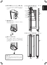
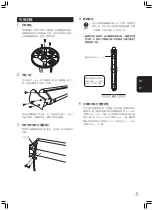
Secure the bottom of the fixture
Using the two provided screws (PMM60P120S), secure
the bottom of the fixture to the speaker through the two
holes shown in the illustration.
12
Attach terminal cover
Place the terminal cover over the bottom of the fixture and
use the furnished screw (PMM60P120S) to secure the
cover in place. When the speaker cords are not passed
through the back of the fixture into a wall, pass the cords
through the gap at the back of the terminal cover.
Regarding the speaker bases
If there is any chance you might want to install the
speakers on the floor again in future, be sure to preserve
the speaker bases safely together with their mounting
screws.
107
(80)
(992)
1072
1041
31
133
60
105
145
43
320
443
520
843
32.5
76.6
900
962.6
(16.4)
70
40
50
85
110
CP-VSL3 Mounting Fixture Hole Dimensions
(unit=mm)
CP-VSL3 Speaker Mounting Dimensions
(unit=mm)
Wall
surface
Mounting holes for fixture to wall
Hole for
temporary
mounting
50x25 square
hole (for attaching
safety strap)
3-
φ
30 holes
(for passing
speaker cord)
8-5.5x9 long
holes (mounting
holes for fixture
to wall)
2-9x15
rectangular
holes
Front
Back
Front view
Side view
3-
φ
5.5 holes
Wall
surface
Front
Back
Front view
Side view
Summary of Contents for CP-VSL3
Page 19: ...19 Ja ...


