22
CX-692
Fig. 27
-
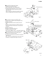
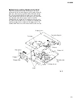
Removing the spindle motor assembly (Fig. 26,27)
1. Similar to the removal procedures for the tray motor
assembly, operate the front lever to move the stage
mechanism to the left end marking on the front lever.
(This will be the first stage.)
2. Turn the tray motor until the clamper fully appears
before moving the tray feeding arm.
* When doing this, remove the flexible PCB from the tray
motor before applying the power(+5V) to the motor
directly to turn the tray motor.
3. Unscrew one screw A to remove the clamp spring and
the clamp.
* When doing this, be careful not to lose the ball being
inserted between the clamper and the clamp spring.
4. Remove the flexible PCB of the spindle motor from its
holder.
5. Unscrew the three screws B to remove the spindle
motor assembly.
* When doing this, be careful not to cut the flexible PCB.
* Note that the disc support arms may be easy to deform.
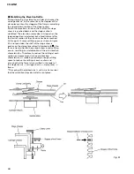
When handling, use special care. (Fig.26)
Fig. 27
Fig. 26
A
Clamp spring
tray feeding
arm
Clamper
flexible PCB
B
B
B
Spindle
motor
assy
Disc support arm
Disc support arm


