6
CX-692
1.5 SERVO SYSTEMS
1.5.1 FOCUSING SERVO SYSTEM
The main equalizer for the focusing servo system is
being provided inside the servo DSP (IC401:TC9461F).
Fig. 7 shows the block diagram of the focusing servo
system.
With the focusing servo system, it is necessary to move
the leans into inside the focusing range to make focus
closing. For this purpose, the lens is moved up and
down by the focus search voltage of the chopping wave
to find out the focusing point. Also, while this
movement is in progress, the SPDL motor is being
kicked to maintain its speed to the preset speed.
The servo DSP works to monitor the FEI signals and the
SBAD signals (upper envelope of the RF) to issue
commands to execute automatic focus closing
movement at the optimum point. Focus closing is
executed when the following conditions are being
satisfied:
1) When the lens moves from "Near" -> "Far" as against
the disc
2) When the FEI signal level exceeds the prescribed
STANDBY level
3) When the FE becomes "0" (FE = "0", at the reference
voltage of 2.1V)
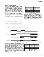
When the SBAD stays beyond the SBREF level
continuously for 32mS after focus closing, the servo LSI
recognizes the focus closed state to raise the FOK port
of the microcomputer to the "H" level.
While if the SBAD stays below the SBREF level
continuously for 12mS after focus closing, the servo LSI
recognizes that the focus is lost to activate the resetting
process.
Meanwhile, the reference voltages for the
aforementioned SBREF level and STANDBY level
coincide the offset levels for respective signals (FEI and
SBAD) for the POWER ON state and for the LD OFF
(CONT = "L") state.
Fig. 8 shows the series of movements relevant to focus
searching and focus closing.
While a 2-layer disc of DVD is being handled, since the
reflectance is low, the focusing error signals will not
exceed the STANDBY level and focus closing is not
workable. In such case, the FE level will be raised
through the OEIC and F-GAIN to start movement to
make the closing motion once again. Since this
movement is not valid under the test mode, it is so
designed that the gain settings for 2-layer DVD discs
can be worked out manually.
B1
B2
B3
B4
RF AMP
IC103
TA1254AF
55
53
54
52
21
FEO
2
3
1
VR21
SERVO DSP
IC401
TC9461F
FEI
FOO
38
43
IC105
NJM3404AM
F.JUMP
CIRCUIT
2
3
1
VR21
VR21
F ACT.
16
17
19
DRIVER
IC304
BA6797FM
IC402
NJM2904M
Fig. 7


