background image

<ENGLISH>

Installation

Note:

• Before finally installing the unit, connect the

wiring temporarily, making sure it is all connected
up properly, and the unit and the system work
properly.

• Use only the parts included with the unit to ensure

proper installation. The use of unauthorized parts
can cause malfunctions.

• Consult with your nearest dealer if installation

requires the drilling of holes or other modifications
of the vehicle.

• Install the unit where it does not get in the driver’s

way and cannot injure the passenger if there is a
sudden stop, like an emergency stop.

The semiconductor laser will be damaged if it
overheats, so don’t install the unit anywhere hot
— for instance, near a heater outlet.

• If installation angle exceeds 60° from horizontal,

the unit might not give its optimum performance.
(Fig. 3)

Fig. 3

60

°

DIN Front/Rear-mount

This unit can be properly installed either from “Front” (conventional DIN Front-mount) or
“Rear” (DIN Rear-mount installation, utilizing threaded screw holes at the sides of unit
chassis). For details, refer to the following illustrated installation methods.

DIN Front-mount

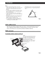
Installation with the rubber bush (Fig. 4)

Fig. 4

Holder
After inserting the holder into the dash-
board, then select the appropriate tabs
according to the thickness of the dash-
board material and bend them.
(Install as firmly as possible using the
top and bottom tabs. To secure, bend
the tabs 90 degrees.)

182

53

Rubber bush

Screw

Dashboard

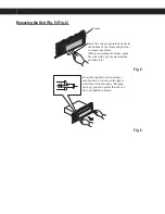
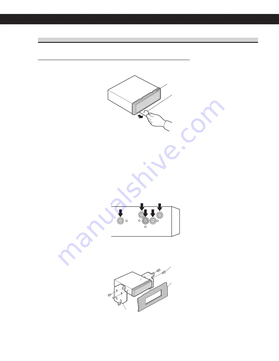
Removing the Unit (Fig. 5) (Fig. 6)

Fig. 5

Fig. 6

5

6

Insert the release pin into the hole in
the bottom of the frame and pull out
to remove the frame.
(When reattaching the frame, point
the side with a groove downwards
and attach it.)

Frame

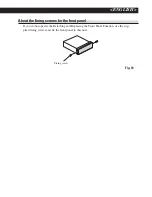
About the fixing screws for the front panel

If you do not operate the Detaching and Replacing the Front Panel Function, use the sup-
plied fixing screws and fix the front panel to this unit.

Fig. 10

DIN Rear-mount

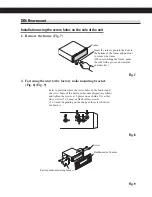
Installation using the screw holes on the side of the unit

1. Remove the frame. (Fig. 7)

Fig. 7

2. Fastening the unit to the factory radio mounting bracket. 

(Fig. 8) (Fig. 9)

Select a position where the screw holes of the bracket and
the screw holes of the head unit become aligned (are fitted),
and tighten the screws at 2 places on each side. Use either
truss screws (5 

×

8 mm) or flush surface screws 

(5 

×

9 mm), depending on the shape of the screw holes in

the bracket

.

Fig. 8

Fig. 9

11

13

12

10

8

9

Frame

Screw

Dashboard or Console

Factory radio mounting bracket

Insert the release pin into the hole in
the bottom of the frame and pull out
to remove the frame.
(When reattaching the frame, point
the side with a groove downwards
and attach it.)

Insert the supplied extraction keys
into the unit, as shown in the figure,
until they click into place. Keeping
the keys pressed against the sides of
the unit, pull the unit out.

Fixing screw

Summary of Contents for DEH-15

Page 1: ...Operation Manual Mode d emploi High power CD player with FM AM tuner Lecteur CD de grande puissance avec syntoniseur FM AM DEH 1500 DEH 15 English Español Français ...

Page 2: ...7 Turning the unit off 7 Tuner Listening to the radio 8 Storing and recalling broadcast frequencies 8 Tuning in strong signals 9 Storing the strongest broadcast frequencies 9 Built in CD Player Playing a CD 10 Playing tracks in a random order 10 Repeating play 10 Pausing CD playback 11 Audio Adjustments Introduction of audio adjustments 12 Using balance adjustment 12 Using the equalizer 12 Recalli...

Page 3: ...al and leave it there Taking a minute to do this now will help to prevent hearing damage or loss in the future After all we want you listening for a lifetime We Want You Listening For A Lifetime Used wisely your new sound equipment will provide a lifetime of fun and enjoyment Since hearing damage from loud noise is often undetectable until it is too late this manufacturer and the Electronic Indust...

Page 4: ...ur listening enjoy ment We recommend that you familiarize yourself with the functions and their operation by read ing through the manual before you begin using this unit It is especially important that you read and observe precautions on the next page and in other sections After sales service for Pioneer products Please contact the dealer or distributor from where you purchased this unit for after...

Page 5: ...tect this product from moisture If the battery is disconnected or dis charged the preset memory will be erased and must be reprogrammed Protecting your unit from theft The front panel can be detached from the head unit to discourage theft Important Never use force or grip the display and the buttons tightly when removing or attaching Avoid subjecting the front panel to excessive shocks Keep the fr...

Page 6: ...BAND button Press to select among three FM and one AM bands and cancel the control mode of functions 7 LOUDNESS button Press to turn loudness on or off 8 LOCAL BSM button Press to turn local function on or off Press and hold to turn BSM function on or off 9 1 6 buttons Press for preset tuning a SOURCE button This unit is turned on by selecting a source Press to cycle through all of the available s...

Page 7: ...ss SOURCE repeatedly to switch between the following sources Built in CD player Tuner Notes When no disc has been set in the unit the source will not switch to the built in CD player When this unit s blue white lead is connected to the car s auto antenna relay control term inal the car s antenna extends when this unit s source is turned on To retract the an tenna turn the source off Turning the un...

Page 8: ... a quick press If you press and hold c or d you can skip broadcasting stations Seek tuning starts as soon as you release the buttons Note When the frequency selected is being broadcast in stereo the stereo 5 indicator will light Storing and recalling broadcast frequencies If you press any of the preset tuning buttons 1 6 you can easily store up to six broadcast frequencies for later recall with th...

Page 9: ...ore the six strongest broadcast fre quencies under preset tuning buttons 1 6 and once stored there you can tune in to those fre quencies with the touch of a button Press LOCAL BSM and hold until the BSM turns on BSM begins to flash While BSM is flashing the six strongest broadcast frequencies will be stored under preset tuning buttons 1 6 in order of their signal strength When finished BSM stops f...

Page 10: ...e CD at a time Do not use an adapter when playing 8 cm CDs Do not insert anything other than a CD into the CD loading slot If you cannot insert a disc completely or if after you insert a disc the disc does not play check that the label side of the disc is up Press CD EJECT to eject the disc and check the disc for damage before inserting the disc again If the built in CD player does not operate pro...

Page 11: ...ard re verse repeat play is automatically cancelled Pausing CD playback Pause lets you temporarily stop playback of the CD 1 Press 6 to turn pause on PAUSE appears in the display Play of the cur rent track pauses 2 Press 6 to turn pause off Play will resume at the same point that you turned pause on Built in CD Player En 11 English Section 05 HHHHHHHHHHHHHH ...

Page 12: ...setting has been previously ad justed BAL will be displayed 2 Press a or b to adjust front rear speak er balance Each press of a or b moves the front rear speaker balance towards the front or the rear FAD F15 FAD R15 is displayed as the front rear speaker balance moves from front to rear FAD 0 is the proper setting when only two speakers are used 3 Press c or d to adjust left right speaker balance...

Page 13: ... level of the equalizer band Each press of a or b increases or decreases the level of the equalization band 6 6 is displayed as the level is increased or decreased You can then select another band and adjust the level Note If you make adjustments when a curve other than CUSTOM is selected the newly adjusted curve will replace the previous curve Then a new curve with CUSTOM appears on the display w...

Page 14: ...lect the fre quency you want to cut Precaution When the F I E function is deactivated the rear speakers output sound of all frequencies not just bass sounds Reduce the volume before disenga ging F I E to prevent a sudden increase in vo lume 1 Press AUDIO to select FIE Press AUDIO until FIE appears in the display 2 Press a to turn F I E on To turn F I E off press b 3 Press c or d to select a desire...

Page 15: ...decreases the source volume SLA 4 SLA 4 is displayed as the source vo lume is increased or decreased Notes Since the FM tuner volume is the control it is not possible to apply source level adjustments to the FM tuner The AM tuner volume level can also be ad justed with source level adjustments Audio Adjustments En 15 English Section 06 HHHHHHHHHHHHHH ...

Page 16: ... or b to set the clock Pressing a will increase the selected hour or minute Pressing b will decrease the selected hour or minute To cancel clock settings press BAND You can also cancel clock settings by holding down AUDIO until the unit turns off Turning the clock display on or off You can turn the clock display on or off Press CLOCK to turn the clock display on or off Each press of CLOCK turns th...

Page 17: ...h discs Avoid touching the recorded non printed side surface when handling the disc Store discs in their cases when not in use Keep discs out of direct sunlight and do not expose the discs to high temperatures Do not attach labels write on or apply che micals to the surface of the discs To clean dirt from a CD wipe the disc with a soft cloth outward from the center of the disc If the heater is use...

Page 18: ... the track skip information are skipped automatically If you insert a CD RW disc into this unit time to playback will be longer than when you insert a conventional CD or CD R disc Read the precautions with CD R CD RW discs before using them Additional Information En 18 Appendix HHHHHHHHHHHHHH ...

Page 19: ... 10 kHz Mid 10 dB 100 Hz 6 5 dB 10 kHz High 11 dB 100 Hz 11 dB 10 kHz volume 30 dB CD player System Compact disc audio system Usable discs Compact disc Signal format Sampling frequency 44 1 kHz Number of quantization bits 16 linear Frequency characteristics 5 20 000 Hz 1 dB Signal to noise ratio 94 dB 1 kHz IHF A net work Dynamic range 92 dB 1 kHz Number of channels 2 stereo FM tuner Frequency ran...

Page 20: ...LTD 178 184 Boundary Road Braeside Victoria 3195 Australia TEL 03 9586 6300 PIONEER ELECTRONICS OF CANADA INC 300 Allstate Parkway Markham Ontario L3R OP2 Canada TEL 905 479 4411 PIONEER ELECTRONICS DE MEXICO S A de C V San Lorenzo 1009 3er Piso Desp 302 Col Del Valle Mexico D F C P 03100 TEL 55 5688 52 90 Published by Pioneer Corporation Copyright 2002 by Pioneer Corporation All rights reserved P...

Page 21: ...Chine CRD3665 A U UC This product conforms to CEMA cord colors Le code de couleur des câbles utilisé pour ce produit est conforme à CEMA Los colores de los cables este producto se conforman con el código de colores CEMA INSTALLATION MANUAL MANUEL D INSTALLATION ...

Page 22: ...t prod ucts such as power amps If you ground the products together and the ground becomes detached there is a risk of dam age to the products or fire Speakers connected to this unit must be high power types with minimum rating of 50 W and impedance of 4 to 8 ohms Connecting speakers with output and or impedance values other than those noted here may result in the speakers catch ing fire emitting s...

Page 23: ...n black Gray black Violet Violet black Front speaker Rear speaker Left Perform these connections when using the optional amplifier With a 2 speaker system do not connect anything to the speaker leads that are not connected to speakers Yellow To terminal always supplied with power regardless of ignition switch position Black ground To vehicle metal body Red To electric terminal controlled by igniti...

Page 24: ...heats so don t install the unit anywhere hot for instance near a heater outlet If installation angle exceeds 60 from horizontal the unit might not give its optimum performance Fig 3 Fig 3 60 DIN Front Rear mount This unit can be properly installed either from Front conventional DIN Front mount or Rear DIN Rear mount installation utilizing threaded screw holes at the sides of unit chassis For detai...

Page 25: ...the frame and pull out to remove the frame When reattaching the frame point the side with a groove downwards and attach it Frame Insert the supplied extraction keys into the unit as shown in the figure until they click into place Keeping the keys pressed against the sides of the unit pull the unit out ...

Page 26: ...nit become aligned are fitted and tighten the screws at 2 places on each side Use either truss screws 5 8 mm or flush surface screws 5 9 mm depending on the shape of the screw holes in the bracket Fig 8 Fig 9 11 13 12 10 8 9 Frame Screw Dashboard or Console Factory radio mounting bracket Insert the release pin into the hole in the bottom of the frame and pull out to remove the frame When reattachi...

Page 27: ...H About the fixing screws for the front panel If you do not operate the Detaching and Replacing the Front Panel Function use the sup plied fixing screws and fix the front panel to this unit Fig 10 Fixing screw ...

Page 28: ......

Reviews: