-
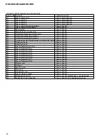
Pin Functions(TA2153FN)
Pin No.
Pin Name
I/O
Function and Operation
1
VCC
Power supply voltage terminal
2
RFGC
I
RF amplitude adjustment control signal terminal
3
GMAD
I
AGC amplifier frequency characteristic adjustment terminal
4
FNI
I
Main beam amplifier input terminal
5
FPI
I
Main beam amplifier input terminal
6
TPI
I
Sub beam amplifier input terminal
7
TNI
I
Sub beam amplifier input terminal
8
MDI
O
Monitor photodiode amplifier input terminal
9
LDO
I
Laser diode amplifier output terminal
10
SEL
I
APC circuit ON/OFF signal, LDO terminal control input terminal and bottom
and peak detection frequency switching terminals
11
TEB
I
Tracking error balance adjustment signal input terminal
12
2VRO
O
Reference voltage (2VRO) output terminal
13
TEN
I
Tracking error signal generation amplifier reverse phase input terminal
14
TEO
O
Tracking error signal generation amplifier output terminal
15
SBAD
O
Sub beam addition signal output terminal
16
FEO
O
Focus error signal generation amplifier output terminal
17
FEN
I
Focus error signal generation amplifier reverse phase input terminal
18
SEB
I
RFRP generation circuit mode switching terminal
19
VRO
O
Reference voltage (VREF) output terminal
20
RFRP
O
Signal generation amplifier output terminal for track count
21
BTC
I
Bottom detection time constant adjustment terminal for RFCT signal
generation
22
RFCT
O
RFRP signal center level output terminal
23
PKC
I
Peak detection time constant adjustment signal for RFCT signal generation
24
RFRPIN
I
Signal generation amplifier input terminal for track count
25
RFGO
O
RF signal amplitude adjustment amplifier output terminal
26
GVSW
I
AGC, FE or TE amplifier gain switching terminal
27
AGCIN
I
RF signal amplitude adjustment amplifier input terminal
28
RFO
O
RF signal generation amplifier output terminal
29
GND
I
GND terminal
30
RFN2
I
RF signal generation amplifier input terminal
1
15
16
30
TA2153FN
72
DEH-P640,P6400,P6450
OUT
GND
VCC
REGULATOR
BPF
GAIN
CONT.
BPF
DET.
REGISTER
PD
NOISE AGC
1
2
3
*TSOP1840SB3V
CS
SK
DI
NC
TEST
DO
GND
VCC
1
2
3
4
8
7
6
5
NC
VCC
CS
SK
DI
DO
GND
TEST
:Not used
:Power supply
:Chip select input
:Clock input
:Data input
:Data output
:Ground
:Test
*PDH0047A(DEH-P6400/XN/UC, DEH-P6450/XN/ES)
Summary of Contents for DEH-P6400
Page 6: ...6 DEH P640 P6400 P6450 2 2 PACKING DEH P6450 13 18 16 1 11 15 17 10 9 8 14 4 6 7 5 2 3 12 ...
Page 8: ...8 DEH P640 P6400 P6450 2 3 EXTERIOR ...
Page 11: ...11 DEH P640 P6400 P6450 ...
Page 12: ...12 DEH P640 P6400 P6450 2 4 CD MECHANISM MODULE D GEM1035 GEM1035 GEM1040 ...
Page 36: ...36 DEH P640 P6400 P6450 A 1 2 3 4 B C D 1 2 3 4 A IC Q A TUNER AMP UNIT ...
Page 37: ...DEH P640 P6400 P6450 5 6 7 8 A B C D 5 6 7 8 37 2 3 4 1 7 6 5 8 SIDE B A ...
Page 41: ...41 DEH P640 P6400 P6450 1 2 3 4 A B C D 1 2 3 4 CLAMP 8EJ SIDE B CONTROL UNIT D D ...


