background image

4

4 - 32

TP #120 v .1.0  2/95

Pioneer DRM-5004X CD-ROM Jukebox User’s Guide

Custom Configuration


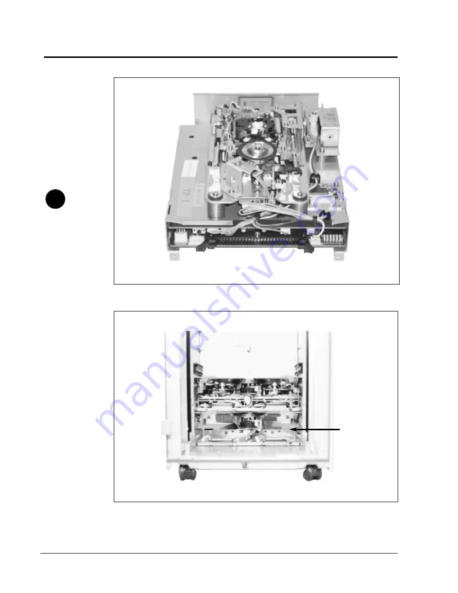
Figure 4-24 Two Pioneer DR-R504X Readers Installed in Drive Bays 1 and 2 of
the DRM-5004X Jukebox.  

The Pioneer DR-R504X Writer may be installed in any

of the four drive bays. In this example it will be installed in Drive Bay 4.

Figure 4-23 The Pioneer DR-R504X CD-ROM Writer

Drive Bay 4

Summary of Contents for DRM-5004X

Page 1: ......

Page 2: ...ormat without written permission from Pioneer New Media Technologies Inc except for normal use by the original buyer s This exception does not allow copies to be made for sale to others Under the law copying includes translating into another language or format Pioneer New Media Technologies Inc is a subsidiary of Pioneer Electronics Corp Notes The information in this document is subject to change ...

Page 3: ...ter 2 15 3 1 Safety Precautions 3 1 3 2 General Operating Conditions 3 1 3 3 Basic Computer Configuration 3 1 3 4 Unpacking the DRM 5004X and Accessories 3 3 3 5 Preparing the DRM 5004X for Operation 3 5 3 6 Loading Discs into the Disc Magazines 3 7 3 7 Loading Magazines into the DRM 5004X 3 9 3 8 Setting the SCSI ID Addresses 3 11 3 9 Enabling Disabling the Disc Transporter Light 3 15 3 10 Starti...

Page 4: ...EPROM Upgrades 6 12 7 1 If the Unit does not Initialize 7 1 7 2 If the SCSI Host Adapter cannot find the Unit 7 1 7 3 If the Computer cannot Communicate with the Drives 7 2 5 6 7 Upgrading Firmware Troubleshooting 4 1 Custom Configuration Options 4 1 4 2 Installing a CD ROM Reader in Drive Bay Three 4 1 4 3 Confirming Proper Installation of the DR D504X 4 23 4 4 Installing a CD R Writer in Drive B...

Page 5: ...rical Characteristics B 1 Pin Assignments B 2 On the DRM 5004X CD ROM Jukebox C 1 On the DR D504X CD ROM Reader C 2 On the DR R504X CD R Writer C 3 Accessing and Interpreting Error Codes D 1 B C D Pioneer Technical Resource Numbers E 1 E A Test Mode Error Codes Pioneer Technical Resource Numbers Product Specifications SCSI Specifications Summary of DIP Switches Jumper Pins ...

Page 6: ...User s Guide Here are some of the highlights of this manual Features of the CD ROM Jukebox DRM 5004X the CD ROM Drive DR D504X and the CD ROM Writer DR R504X are fully described You will find detailed instructions for setting up and testing the DRM 5004X with a basic two reader configuration There are step by step instructions to custom configure the unit by installing additional Pioneer CD ROM Re...

Page 7: ...bodily harm CAUTION The symbol of a triangle with an exclamation mark inside is intended to alert the user to important operating and maintenance instructions in the literature accompanying this product Failure to follow instructions contained in the CAUTION statement could cause damage to the unit or to other equipment NOTE The symbol of a check mark within a black box indicates some information ...

Page 8: ...and ing of the unit s features and where they are located 3 Setting Up the DRM 5004X A Basic Two Reader Configuration This chapter provides the steps to follow to set up the DRM 5004X CD ROM Jukebox with two readers installed It reviews basic safety precautions unpacking the unit loading discs into magazines insert ing magazines into the unit setting the SCSI ID switches making the SCSI connection...

Page 9: ...ukebox and the Writer contain EEPROMs that can be upgraded by downloadinig software The Writer also requires replacement of an EPROM The Reader is upgraded by replacing the EPROM 7 Troubleshooting Here are steps to follow to help you troubleshoot problems What if the unit will not initialize and you do not see the green LED signifying that power is on and the unit is ready to operate If the SCSI h...

Page 10: ......

Page 11: ......

Page 12: ......

Page 13: ......

Page 14: ......

Page 15: ...er drive bays The two additional lower drive bays can accommodate optional Pioneer CD ROM Readers DR D504X or Pioneer CD ROM Writers DR R504X NOTE Any combination of Pioneer CD ROM Readers and or Writers can be installed in the four drive bays Install the drives in consecutve drive bays starting with drive bay one In the default configuration the drive units and the changer mecha nism are daisy ch...

Page 16: ... or the unit will not initialize Store the shipping plates inside the front door panel for re use when the magazines are removed Magazines should be installed from the bottom of the unit first If space for a magazine is not filled but left empty discs in the upper magazines cannot be accessed See Chapter 2 Features for more details CAUTION NEVER SHIP OR TRANSPORT THE DRM 5004X CD ROM JUKEBOX WITH ...

Page 17: ... addressed independently on its own SCSI chain so writing a CD R disc can take place without interruption 1 1 7 SCSI Connections There are a total of five SCSI ID Setting Switches on the rear panel of the unit one to set the SCSI address of each drive installed and one to set the SCSI address of the changer mechanism There are six SCSI connectors on the rear panel Typically when the unit is shippe...

Page 18: ...Jukebox Next the host computer selects the SCSI ID of the drive unit containing the disc It then sends CD ROM commands to read data from the disc If a DOS machine is used as a host computer there will be two or three device drivers installed one for the Jukebox one for CD ROM Readers and one for CD R Writers For other computer operating systems consult with specific software vendors 1 1 11 Writing...

Page 19: ...t be correctly inserted before any vertical movement within the changer can take place NOTE If the front door is opened during initialization mechanical movement is stopped immediately After the door is closed initializa tion can be resumed by powering off and then powering on the unit Position of the disc magazines and the presence or absence of shipping plates is checked by infra red IR sensing ...

Page 20: ... in either the left or right side of the magazine 3 The arm is extended to a disc slider movement 4 A disc is grasped 5 The arm is retracted slider movement 6 A swing motor with disc is returned to center position 7 The disc transporter is moved to drive position 9 A disc is grasped 8 The swing motor is rotated to face a drive 10 The arm is extended to place disc in drive 11 The disc is released a...

Page 21: ......

Page 22: ...04X often includes two 4X speed Pioneer CD ROM readers the DR D504X The DRM 5004X can accommodate any combination of up to four Pioneer CD ROM readers DR D504X or Pioneer CD R writers DR R504X The changer controller and the built in CD ROM drive are connected by a SCSI daisy chain The DRM 5004X Jukebox has a flash memory for easy firmware upgrade via software NOTE Drives can also be connected on i...

Page 23: ... e h e W Y fI K I46K I e 6X h e W Y f V W 6X I46K V e X e W Y LgV4 Ke I 6K h eJ W Y 3 X gI UW 6KeV4 6K 0Y h e7 W Y V Xg V UI 6XeI4 6K g J e W Y V X gV4 KS K eI4 6K g 75 e W Y V XhI UI4 6K eI4 6K g H e 5 W Y V X g V4 K I 6K eI4 6K f H W Y V Xh I46KS 6X eI4 6X f W Y V K h I UI4 KfI4 f W Y V4 6X hV4 K I4 6Kg O2 6K g f W Y I XheI 6K I4 6K O2 6K e J W Y V K h V4 6X I4 6Khe O2 0MgI4 6X g e 7 W Y V 6X h ...

Page 24: ...r viewing indicator lights See Figure 2 1 Front View of the DRM 5004X CD ROM Jukebox 1 Display The window allows the LED display to be seen 2 Door The door opens to allow access to internal elements 3 Casters Casters allow the DRM 5004X to be moved by rolling the jukebox Casters lock to prevent the jukebox from rolling or being shifted Also see Figure 2 2 Locking and Unlocking Casters 4 Power Indi...

Page 25: ... fW L hg h W he 5 5 3 g L f J 5 e W 1 hg h 7 e he H H N h KfO H e 7 Y hg 3 5 hJ 5e he L J g 7 fJ Y L hf H g W He he L 1 7 g e W He 1 hf 7 hW e Lhe 1 J 5 g 3 e 7 L J L 5 hf J 3 h X h3 L 7 H 3 L J 5h gI L X H hf 7 N hV4 hN 1 J 5 N 1 W Hg 7 g N 1 1 hg J L heI4 Y h 3 L W H 3 L W g L g hg 7 K Hhe N K he O 5 V K he O 5 g 1 g gI M L hf g hf 6K g O2 Y V 6K g O2 Y g g g N H 1 hf 3 5 g3 5 hf I H V 6 2 Yh 5 ...

Page 26: ...6 Power Switch Switch to turn power on to the DRM 5004X 7 Mode Setting Buttons See Figure 2 6 Inside Front Panel Switches A Mode Setting Buttons These buttons are used to set the values of the SCSI ID and commands the Display to pro vide other information for example the total disc exchange times See Section 3 8 2 page 3 13 These buttons are also used for Test Mode See Chapter 5 for details 8 Rota...

Page 27: ...J hf he 3 L H 7 Hhe hf he V L 3 1 J 5 he N hf hfN 1 V L L 7 H hf hf hf 3 L N 1 J 5 hf 5 hf N 1 3 L H 7 H hf H 3 L N 1 J 5 hf N 1 3 L W H hf 3 L N 1 7 5 hf N 1 3 L H hf 3 L N 1 J 5 hf N 1 3 L W Y hf 3 L N 1 7 H hf N 1 3 L hf 3 L N 1 J 5 hf N 1 3 L W Y hf 3 L N 1 7 H hf N 1 3 L J 5 hf 3 L N 1 7 H hf V 1 3 L J 5 hf N L N 1 7 H hf 31 3 L J 5 hf N L N 1 7 H hf 31 3 L J 5 hf N L N 1 7 H hf 1 3 L J 5 hf ...

Page 28: ...two CD ROM Readers are connected by a daisy chain between connectors A and B with a terminator block installed on connector B Connectors C D E and F can be used for custom configurations 2 SCSI ID Switch These DIP switches are used to set SCSI IDs of the changer mechanism and the installed CD ROM drives 3 Audio Output Terminal These output the digital audio signal from standard CD ROM and CD DA di...

Page 29: ...0Y O M I Kf X f O R KV H I T MI XI US US S KV M 1 H O2 0Y V 6T Ke O2 C N Y N1 N R R MB R40R YW R MB R Y 5 O2 0M V4 T 6T 6X J LV LeC L f Yf Y H O2 0M S UI T X S S T2 X W T2 0Y L L O2 0M XV R40 MI U US 5 S U US U S W R 0M 31 heW2 6K O2 0M X g N Y e B YeI R40R U R V R40R YW 0M H N he7 6K O2 0M 7 S XeO T26T U T J eJ H e N X O 0M Lh J M I4 6Kg O2 0M W2 T2 S U UO T T KO T T X fO 2 0Mg X L 3 X gW Yg I4 0...

Page 30: ... or damage this sensor 7 Shipping Plate The shipping plate locks the discs into the disc magazine to prevent them from slipping out while moving the disc magazine CAUTION Do not ship or store the magazines with discs loaded Also do not ship the DRM 5004X with discs inside the magazines or with magazines installed 2 1 4 Disc Transporter The disc transporter is the mechanism that moves discs between...

Page 31: ...D504X CD ROM Reader Figure 2 14 Basic Two Reader Configuration within the DRM 5004X Jukebox 2 2 10 TP 120 v 1 0 2 95 Pioneer DRM 5004X CD ROM Jukebox User s Guide Features Drive 1 Installed Drive 2 Installed Drive Bay 3 Empty Drive Bay 4 Empty ...

Page 32: ...KBytes sec at 4X rotational speed The DR D504X has a look ahead buffer of 128 KBytes Stereo output is supported with this drive unit It can be inter nally connected to the audio output pin jacks L R attached on the connector board of the jukebox 2 2 1 DR D504X Reader Configuration The basic configuration of the DRM 5004X Jukebox often includes two DR D504X Readers It can be custom configured howev...

Page 33: ...ader Features Top View Front View Rear View 1 Servo Mechanism 13 Cable Connector 2 Shield Casing 3 Optical Head 4 Spindle Motor 5 Setting SCSI ID Connector 6 Controller Connector 9 Audio Connector 7 Power Connector 8 SCSI Connector 10 Terminator Switch 12 Spindle Board 11 Servo Mechanism Boards 11 Servo Mechanism Boards ...

Page 34: ...the rear panel of the DRM 5004X and to convey the SCSI ID setting to the Reader 6 Controller Connector This 5 pin connector attaches the DR D504X to the controller board and conveys drive presence and clamp status to the main CPU 7 Power Connector This 9 pin connector attaches the DR D504X to the DRM 5004X and the power supply 8 SCSI Connector This 50 pin connector attaches the DR D504X to the SCS...

Page 35: ... DR R504X CD R Writer Figure 2 17 Two Pioneer Drives in the Two Upper Drive Bays of the DRM 5004X Placement of the DR R504X Writer within the DRM 5004X Drive in Drive Bay 1 Drive in Drive Bay 2 Note A Pioneer DR R504X Writer can be installed into any of the four drive bays DR R Writer to be installed into Drive Bay 4 ...

Page 36: ...e daisy chained to other SCSI devices The DR R504X has a high speed data transfer rate of 614 KBytes sec at 4X high rotational speed The DR R504X has a large data buffer of 1 MByte The DR R504X has a flash memory EEPROM for easy firmware upgrade via software 2 3 1 DR R504X Writer Configuration The DRM 5004X basic configuration typically includes two DR D504X Readers The unit may be custom configur...

Page 37: ...5 Pioneer DRM 5004X CD ROM Jukebox User s Guide Features Front View Top View 1 Servo Mechanism 3 Optical Head 4 Spindle Motor 5 Setting SCSI ID Connector 6 Controller Connector 9 DIP Switches 8 SCSI Connector 7 Power Connector DIP Switches are numbered from left to right 1 2 3 4 5 6 ...

Page 38: ...e writer 6 Controller Connector This 5 pin connector attaches the DR R504X to the controller board and performs the clamp and unclamp functions 7 Power Connector This 9 pin connector attaches the DR R504X to the DRM 5004X and the power supply 8 SCSI Connector This 50 pin connector attaches the DR R504X to the SCSI chain at the rear of the DRM 5004X 9 DIP Switches All switches are set in the down p...

Page 39: ......

Page 40: ...to protect the DRM 5004X and its components from damage 3 2 General Operating Conditions The following conditions for temperature and relative humidity should be met for operating and storing the DRM 5004X Temperature and Relative Humidity Operating non condensing Temperature 5 40 0 C 41 104 0 F Maximum gradient of 10 0 C Hour Humidity 10 80 RH Maximum gradient of 10 RH Hour Max Wet Bulb Temperatu...

Page 41: ... W H O2 0M f O X V X heC Y h 6K W YhW W2 0M g W2 0M eI4 X V Xh Yhe I4 6K g W Y g W M 7 0M hW 0M gI 1 V X gJ Y I4 6KfW Hh 7 H 3 he W he V4 V Xf W Hh O2 6K eI4 6KO 5 hJ 5 N h 7 5 I V X eW 5 f O2 6X eI4 0Y g W Y h Y V X W Y e W2 0MgI4 KgI M hW Y I f H V HfW 0M he I 6X W Y V L e 5 V e W V X hf 7 Y V KeJ Y O2 eO 5 V Xhf H N 6 Y O2 0M 5 Y V X h 5 H O2 0M e H 6K V 1 h I O2 0M g J MI4 6KhfV Lh 1 N L O2 0M...

Page 42: ...rience service delays The disc magazines are shipped with five shipping plates in a second box See Figure 3 2 Accessories Shipped with the DRM 5004X 3 4 2 Unpacking the DRM 5004X and Accessories Remove the DRM 5004X and the accessories from the box and confirm that all of the accessories listed in Section 3 4 1 Accessory List are included If any of the accessories are missing contact your vendor 1...

Page 43: ...f J MI X g J 0 1e V X he g hfO H V X J g 5 7 e V L 3 5 V Xhe g heW2 fN X g H fN 1 V Y eV K h g h W L e V 1 N g L fJ 5 g V 6K g g hO Y N KO2 N L g 1 3 e O H hV4 6X f g gO2 Ye 3 5e g N hfI Kf g fO2 0Y e V4 0Ye H g 0M hf V4 6K g O2 0M 5 J g I4 Y 7 g 5 W V40Y g W2 U I4 0M f g 1 7 1 3 g 5 e g H e 7 g J LeJ g 7 KO 5 5 g 3 L J Y H g N 1 W H J g 5 7 e 7 g H e J O2 g 3 7 g J V4 3 0M g 7 I4 0M V M g g g g 3...

Page 44: ...ould be set to the OFF position factory default If the DIP switches are not set to the OFF position switch them to OFF See Figure 3 4 Switches on Inside Front Rail A 5 Check the rotary switch on the inside front rail It should be set to 0 If it is not set to 0 rotate the switch until it reads 0 See Figure 3 4 Switches on Inside Front Rail B 6 Connect the power cord to the DRM 5004X and do not yet ...

Page 45: ...3 Disc Stopper 3 3 6 TP 120 v 1 0 2 95 Pioneer DRM 5004X CD ROM Jukebox User s Guide Set Up Figure 3 7 Shipping Plate Insertion and Removal Figure 3 9 Storing Shipping Plates Inside Front Door Figure 3 8 Disc Insertion and Removal Top of Magazine Labeled side of Disc Inside Front Door Shipping Plates on Brackets ...

Page 46: ...oneer CAUTION Follow disc installation and removal procedures specified by the system application There are no disc sensors at individual disc storage locations so disc presence must be managed in memory Make sure that the discs do not cross over into another slot To avoid mis insertion do not insert or remove discs while the magazine is mounted in the changer The elevator must be at the bottom po...

Page 47: ...4X CD ROM Jukebox User s Guide Set Up Figure 3 10 Grasp the Magazine with Fingers Extended Figure 3 11 Loading a Magazine into the DRM 5004X Lock Release Levers Top of Magazine Encoder Sensor Plate Avoid touching this plate Do not damage it ...

Page 48: ... the unit and then powering it back on Then power off the unit and proceed with installa tion of magazines 4 Grasp the sides of the magazine with fingers fully extended Use your index finger to release the lock release levers on each side See Figure 3 10 Grasp the Magazine Do not touch the stainless steel Encoder Sensor Plates on sides of the magazine 5 Slide the magazine into the DRM 5004X using ...

Page 49: ...g 1 SCSI Interface Connectors 2 SCSI ID Switch 3 Audio Connectors 6 Power Connector 4 Voltage Selector Switch 5 GND Terminal SCSI Cable for Drive 2 SCSI Cable for Drive 1 SCSI Cable for Drive 4 SCSI Cable for Drive 3 Disc 1 Disc 2 Disc 50 Disc 51 Disc 49 Disc 100 Disc 101 Disc 102 Disc 149 Disc 150 Disc 200 Disc 151 Disc 401 Disc 450 Disc 449 Disc 500 Drive 1 Installed Drive 2 Installed Magazine 1...

Page 50: ...ing SCSI IDs using the DIP switches The Pioneer DRM 5004X CD ROM Jukebox has five SCSI ID switches on the rear connection board The first four switches set the SCSI IDs assigned to the individual CD ROM drives installed in the unit and the last switch sets the SCSI ID assigned to the changer mechanism con troller See Figure 3 12 SCSI ID Switch Settings Figure 3 13 Front View of Disc Addresses for ...

Page 51: ...et In SCSI ID Setting Mode NOTE The SCSI IDs set using front panel buttons must match those set with DIP switches on the back of the unit Figure 3 17 Pressing an R button will cycle through 0 F to set SCSI ID 0 1 2 3 4 5 6 7 F 1 2 3 4 0 1 2 3 4 0 SCSI ID SW DISPLAY L1 L2 L3 L4 R1 R2 R3 R4 1 3 2 4 Display Mode Setting Keys D1 D2 D3 D4 D5 D6 Mode Setting Buttons 5 5 ...

Page 52: ...ights up 2 Press L2 key to enter SCSI ID Setting Mode This allows you to manually set the SCSI ID Switches so the player will know how to respond to software that queries the unit for SCSI ID numbers of the different drives Make sure the numbers match those set with SCSI ID switches on the rear connection board See Figure 3 16 SCSI ID Numbers set in SCSI ID Setting Mode Also see Figure 3 17 Pressi...

Page 53: ...r lights are located beside the display window on the inside top rail of the DRM 5004X Green Red Display Window SCSI Cable from DRM 5004X to Computer using Connector A Terminator Block Connected to Connector B Power Cord Figure 3 18 Location of Jumper to Enable Disable Disc Transporter Light Jumper Pin on Main Power Board One pin set to OFF disables the Disc Transporter Light The other pin set to ...

Page 54: ... Move jumper pin from the off pin to the on pin 6 Replace the top rear panel of the DRM 5004x 7 Reconnect the Power cable 3 10 Starting Up the DRM 5004X for Operation After the magazines with discs have been loaded and the proper SCSI cable terminator and power cable have been securely attached the DRM 5004X can be started Refer to Figure 3 19 Rear Connection Board With Cables Connected and then f...

Page 55: ... f 1 e 5 g 0Y e e I4 0M V eI40M e h g 5 e f g H e e g 3 L e 1 g V 1 e 5 g 6K he e hf g 6Xf W2 e e g e g 1f 7 O KO2 e 5 e H g L eJ e O2 6KfO2 6XeO2 6X W2 6X W 6Xe 6Xhe 0M f H e L g 1 e7 e 1 1 1e 4 1heV4 0 4 0 M he I Me I Mhf f hf g e e 0M Me 5 V Me f W Y N Me J Ye f he g L J g H e g fW H e f 7 W f h g 1 7 eW2 f W2 e W 5f 1 e 7 L e 3 5 e7 0Y L e 7 eW eW Ye J e X e 1 g N H e e Ke 1 O O Y e 7 e 3 KO2 ...

Page 56: ...f inside front right rail 3 Insert door switch bypass jig into door lock hole to hold switch closed during testing Call Service for information 4 Locate the TM button on the inside front right rail above door interlock switch Figure 3 21 Mode Setting Buttons and Display 5 With door switch bypassed press the TM button and hold for three seconds or until the Display shows 00_xxx 6 Test Mode is now e...

Page 57: ... Unit Installation Status In this example two drives are installed and no magazines Figure 3 25 Status Display for DIP Rotary Switches MODE SUBMODE BLANK DRIVES INSTALLED 1 2 NOTE Numbers in the small boxes indicating drives installed do not appear on the display MODE SUBMODE BLANK FRONT SWITCHES Reserved Test Mode Setting Buttons TM MD SM SM S1 S2 S3 S4 ...

Page 58: ...ning characters show the num ber of drives recognized o o indicates two drives o 8 or 8 o indicates three drives 8 8 indicates four drives Periods between characters indicate magazines are not present 3 If the display shows an incorrect number of drives repeat steps 1 and 2 Confirm with a visual check of the drive bays at the bottom of the changer If the problem still occurs contact Service 3 11 4...

Page 59: ...g Mode A to 5 Magazine 5 Magazine 4 Magazine 3 Magazine 2 Magazine 1 Drive 1 Drive 2 Drive 3 Drive 4 1 50 51 100 101 150 151 200 201 250 251 300 301 350 351 400 401 450 451 500 507 521 514 528 Vertical Addresses in Test Mode Drive Addresses in Test Mode Drive Addresses in Test Mode MODE SUBMODE BLANK DISC LOCATION Test Mode Setting Buttons TM MD SM SM S1 S2 S3 S4 MODE SUBMODE BLANK NUMBER OF CYCLE...

Page 60: ...est slot 1 is the upper left slot and slot 500 is the lower right slot See Figure 3 26 Vertical Addresses Used in Test Mode Use the Pioneer Disc Setting Tool to insert discs into the magazine NOTE Remove the magazines to load discs If there are discs in the magazine install the shipping plate before moving the magazine Remove the shipping plate to remove or load discs and again after the magazines...

Page 61: ...er s Guide Set Up Figure 3 29 Return to Aging Mode A Press S4 to execute 5 cycles Test Mode Setting Buttons TM MD SM SM S1 S2 S3 S4 MODE SUBMODE BLANK DISC LOCATION Figure 3 30 Aging Mode A Completes Five Cycles Without Errors MODE SUBMODE BLANK NUMBER OF CYCLES ...

Page 62: ... the flashing LED display at the top of the inside front top rail The display will read XX_xxx The XX is the hex code of the operation when the error occurred The xxx is the cycle count when the error occurred To obtain detailed information about the error refer to Chapter 5 Test Mode Section 5 2 or 5 3 Also see Appendix D Test Mode Error Codes NOTE Check the condition of the unit should an error ...

Page 63: ... DRM 5004X CD ROM Jukebox User s Guide Set Up Figure 3 31 Green and Red LED Indicator Lights The green and red LED indicator lights are located beside the display window on the inside top rail of the DRM 5004X Green Red Display Window ...

Page 64: ...irectory 4 Execute SCSI5ASP EXE to load the software utility onto the inspection computer Press any computer key to access the main menu from the program start up Press the key to call up the CHANGER menu 5 Press the 5 to select the SCSI ID for changer control mecha nism The default is 5 If changed select the correct number 6 Use the cursor arrow keys to select INQUIRY from the CHANGER menu Press ...

Page 65: ...K g W Y g W M 7 0M hW 0M gI 1 V X gJ Y I4 6KfW Hh 7 H 3 he W he V4 V Xf W Hh O2 6K eI4 6KO 5 hJ 5 N h 7 5 I V X eW 5 f O2 6X eI4 0Y g W Y h Y V X W Y e W2 0MgI4 KgI M hW Y I f H V HfW 0M he I 6X W Y V L e 5 V e W V X hf 7 Y V KeJ Y O2 eO 5 V Xhf H N 6 Y O2 0M 5 Y V X h 5 H O2 0M e H 6K V 1 h I O2 0M g J MI4 6KhfV Lh 1 N L O2 0M h 7 Yf I4 6K h V X g 5 K O2 0Mhf H g I4 6KhN 1 gJ Y 6X O2 0M L hf I4 6...

Page 66: ... power down control computer 3 Disconnect the DRM 5004X from the power source 4 Disconnect the DRM 5004X from the control computer 5 Remove the SCSI cable from the DRM 5004X 6 Remove the power cord from the back of the DRM 5004X 7 Remove the SCSI bus terminator from Connector B 8 Repack all accessories into packing envelope 9 Remove all magazines from DRM 5004X remove all discs from magazines repa...

Page 67: ......

Page 68: ...gh their own indi vidual SCSI ID addresses A reader can be installed separately on its own SCSI bus however then it does not have access to the changer mechanism A writer is usually installed on its own individual SCSI bus so there are no interruptions while data is written to a CD R disc See Section 4 8 Making SCSI Connections and Section 4 9 Optional SCSI Connections Any combination of readers a...

Page 69: ...r showing DIP Switches for Termination DR D504X set to Left Orientation DR D504X set to Right Orientation Front of DR D504X Reader 5 Setting SCSI ID Connector 6 Controller Connector 9 Audio Connector 7 Power Connector 8 SCSI Connector 10 Terminator DIP Switches 11 Servo Mechanism Boards Jumper Pins at back of board Pins are num bered from left to right 1 2 3 4 5 6 Pin 6 sets the sector size Jumper...

Page 70: ... bay The unit is shipped with a right orientation See Figure 4 1 Orientation of the DR D504X CD ROM Reader See Page 4 5 for procedure B Set the jumper pins on the circuit board of the reader for sector size to either 2048 or 512 bytes The factory set default is 2048 bytes See Figure 4 2 Jumper Pins on Circuit board of DR D504X See page 4 7 for procedure C If necessary set termination on the reader...

Page 71: ...the DR D504X reader from Right to Left DR D504X Orientation for Placement in the Left Drive Bay DR D504X Orientation for Placement in the Right Drive Bay Black Screws Grey and Blue Wires Front of DR D504X Three Black Screws Grey and Blue Wires Front of DR D504X Black Screw Servo Mechanism Optical Head Spindle Motor ...

Page 72: ...rter can catch them as it moves within the DRM 5004X 3 Re orient the drive as shown below by rotating the servo sec tion A flexible cable from the pickup is located in the cen ter of the servo section so do not pull up on the servo sec tion as you rotate it 4 Carefully align two positioning holes in the servo section before tightening screws There is a small bubble in the shielded chassis that als...

Page 73: ...r Size with Jumper Pins Carefully pull circuit boards apart Setting SCSI ID Connector Controller Connector Audio Connector Power Connector SCSI Connector Terminator Switch Servo Mechanism Boards Screws Back set of wires to detach Jumper Pins Numbered from left to right 1 2 3 4 5 6 SCSI Connector on front of Board 1 2 3 4 5 6 ON OFF Jumpers ...

Page 74: ...ware and the green jumper pins When you look at the lower board from the front with the SCSI connector facing you the jumper pins will be located at the far end of the board The pin at the right side 6 sets the sector size The default is all pins jumpered Jumpered sets pin 6 for 2048 bytes If you remove the pin from either post the sector size will be set at 512 bytes For more information on these...

Page 75: ...oneer DRM 5004X CD ROM Jukebox User s Guide Custom Configuration Figure 4 6 Front View of DR D504X Reader Terminator DIP Switches Expanded view of Terminator DIP Switches Both switches are in the down position ter mination is ON ...

Page 76: ...04X before changing the termination setting or you may blow a fuse NOTE If the terminator fuse inside the unit is blown by connecting or removing the terminator block or a SCSI cable while the power to the unit is on the last drive on the chain can be terminated to provide termination temporarily To replace fuse call Service See Appendix E Pioneer Technical Resource Numbers Refer to Figure 4 6 Fro...

Page 77: ...X W 6Xe 6Xhe 0M f H e L g 1 e7 e 1 1 1e 4 1heV4 0 4 0 M he I Me I Mhf f hf g e e 0M Me 5 V Me f W Y N Me J Ye f he g L J g H e g fW H e f 7 W f h g 1 7 eW2 f W2 e W 5f 1 e 7 L e 3 5 e7 0Y L e 7 eW eW Ye J e X e 1 g N H e e Ke 1 O O Y e 7 e 3 KO2 f 5 hf g 3 5e3 e L 3 5 3 e V4 1 e g V YeV e V4 H V4 0M I M e g g e M g 5 e 1 YO2 g V4 0Y e 5 e e hf e g e h e g e H X g e L K O2 g e 0M e 0M H O2 g L e O ...

Page 78: ...t Mode Call Service for information 3 Enter test mode by pressing the top left button marked TM on the inside front panel Hold the TM button for five seconds or until Ò00 xxxÓ appears on the display 4 Instruct the changer mechanism to move the disc transporter to address 401 Enter Mode 4 Step Operation by pressing the button second from the top on the left hand side 4 times In Test Mode this butto...

Page 79: ...e Disc Transporter Manually This is a view of the DRM 5004X from the front showing four drives installed and no magazines loaded The disc transporter can be raised manually to allow access to the drive bays NOTE The top magazine must be removed to reach the gear mechanism that is used to raise the disc transporter ...

Page 80: ...ing the Disc Transporter Manually 1 Power Off the DRM 5004X 2 Remove the power cord 3 Place shipping handle into top magazine 4 Remove the top magazine 5 Reach into the small opening in the far top right rear corner of the inside of the DRM 5004X 6 Move the gear clockwise with index finger to raise the disc transporter 7 Move the gear counter clockwise to lower the transporter Custom Configuration...

Page 81: ... 4 9 Clamper Assembly Details On the Clamper There are 3 screws 2 are located on the front of the clamper at the edges the third screw is located in the center of the assembly beneath the white connectors White Connectors Gears to Unclamp Discs Side Screws Side Screws Front Inside View of DRM 5004X ...

Page 82: ... you can slide it out by hand If the disc cannot be removed rotate the large black gear in the center to unclamp it The gear can be rotated in either direction After the disc is raised in an unclamped position it can be removed by hand 5 Disconnect the white connector in the center of the clamper assembly 6 Use a magnetic screwdriver and remove two side screws on the clamper assembly 7 Use a magne...

Page 83: ...nstalled Drive Bay 3 Empty Drive Bay 4 Empty SCSI Cable for Drive 2 SCSI Cable for Drive 1 SCSI Cable for Drive 4 SCSI Cable for Drive 3 Figure 4 11 SCSI Cable Connectors Used to Connect the Drives to the DRM 5004X Front View of the DRM 5004X Inside Rear View of the DRM 5004X Inside the Lower Panel Cover SCSI Connector for the DRM 5004X Changer Mechanism ...

Page 84: ...le on the right with three pins and there is one cable toward the top of the unit with nine pins These connections should match those made on the standard reader installed in the bay above CAUTION If you push too hard you can bend the pins or crack the plastic housing or connector wire casings Also secure the cables of the right and top connectors so they are flush against the drive Tie them with ...

Page 85: ...ed Posts Post 1 Powered Post 4 Non powered Post 3 Non powered Post 2 Powered Unpowered Posts Powered Posts Post 1 Powered Post 4 Powered Post 2 Powered Post 3 Powered WARNING If you later remove the drives you have enabled power for make sure to remove power from their respective power posts If power remains connected and the drives are removed the unit will be damaged ...

Page 86: ...he right side provide power those to the left are non powered 4 Move the non powered connector for drive bay 3 to its corre sponding powered post Leave the connectors for empty drive bays on the non powered posts 5 Replace the rear Upper Panel Cover and re attach screws 6 Reconnect the power cable to the wall outlet 7 Power ON the DRM 5004X 8 Confirm that the reader is receiving power by looking d...

Page 87: ...4 4 20 TP 120 v 1 0 2 95 Pioneer DRM 5004X CD ROM Jukebox User s Guide Custom Configuration This page has been intentionally left blank ...

Page 88: ... OFF 512K C If necessary set Termination on the Reader 3 Raise the Disc Transporter Using Test Mode or Manually 4 Remove the Lower Clamper Assembly 5 Remove the Drive Bay Covers 6 Install the Additional Reader into Drive Bay 3 NOTE Readers can be installed into any of the four drive bays 7 Replace the Lower Clamper Assembly 8 Enable Power on the Rear Power Board for the Reader installed in drive b...

Page 89: ...f H e e g N 1 f He7 e hf 6Kf e 3 H L 1 N KO2 f L e 1 g O2 5 e e hf 6 2 e V4 e 3 f 1 e 5 g 0Y e e I4 0M V eI40M e h g 5 e f g H e e g 3 L e 1 g V 1 e 5 g 6K he e hf g 6Xf W2 e e g e g 1f 7 O KO2 e 5 e H g L eJ e O2 6KfO2 6XeO2 6X W2 6X W 6Xe 6Xhe 0M f H e L g 1 e7 e 1 1 1e 4 1heV4 0 4 0 M he I Me I Mhf f hf g e e 0M Me 5 V Me f W Y N Me J Ye f he g L J g H e g fW H e f 7 W f h g 1 7 eW2 f W2 e W 5f...

Page 90: ...r of inside front right rail 3 Insert door switch bypass jig into door lock hole to hold switch closed during testing Call Service for information 4 Locate the TM button on the inside front right rail above door inter lock switch Figure 4 13 Mode Setting Buttons and Display 5 With door switch bypassed press the TM button and hold for three seconds or until the Display shows 00_xxx 6 Test Mode is n...

Page 91: ... of Display Illuminated Figure 4 16 Unit Installation Status Figure 4 17 Status Display for DIP Rotary Switches MODE SUBMODE BLANK DRIVES INSTALLED 1 2 3 NOTE Numbers in the small boxes indicating drives installed do not appear on the display MODE SUBMODE BLANK FRONT SWITCHES Reserved Test Mode Setting Buttons TM MD SM SM S1 S2 S3 S4 ...

Page 92: ......

Page 93: ...or Aging Mode A to 5 Magazine 5 Magazine 4 Magazine 3 Magazine 2 Magazine 1 Drive 1 Drive 2 Drive 3 Drive 4 1 50 51 100 101 150 151 200 201 250 251 300 301 350 351 400 401 450 451 500 507 521 514 528 Vertical Addresses in Test Mode Drive Addresses in Test Mode Drive Addresses in Test Mode MODE SUBMODE BLANK DISC LOCATION Test Mode Setting Buttons TM MD SM SM S1 S2 S3 S4 MODE SUBMODE BLANK NUMBER O...

Page 94: ......

Page 95: ...ser s Guide Custom Configuration Figure 4 21 Return to Aging Mode A Press S4 to execute Aging Mode A for 5 cycles Test Mode Setting Buttons TM MD SM SM S1 S2 S3 S4 Figure 4 22 Aging Mode A Completes Five Cycles Without Errors MODE SUBMODE BLANK NUMBER OF CYCLES ...

Page 96: ......

Page 97: ...4 4 30 TP 120 v 1 0 2 95 Pioneer DRM 5004X CD ROM Jukebox User s Guide Custom Configuration This page has been intentionally left blank ...

Page 98: ......

Page 99: ...tion Figure 4 24 Two Pioneer DR R504X Readers Installed in Drive Bays 1 and 2 of the DRM 5004X Jukebox The Pioneer DR R504X Writer may be installed in any of the four drive bays In this example it will be installed in Drive Bay 4 Figure 4 23 The Pioneer DR R504X CD ROM Writer Drive Bay 4 ...

Page 100: ...N e W Yhe V4 HhfV K W YheN1 g 7Hh 3L O20Y O2 X e 7H hf I4 hf V46T H he 3L g J5 h N T20M f O2 6KO20Y X eJ5 I4 hf N1 g 7H he 0M f O2 0MfI4 0M 3 X hf 3 O Y 3L g J5 W2 M hf V Xhf N Y O2 6K V X g hf W Y W Y V X he HhfW2 gO2 0M I4 6K N1 g hf 7H 7 Y eO2 6Kg V Xhe hf7 W e W2 0Mg I46X 3L g hfJ5 J YeO2 6KgV 1he 3Lhf O eO M e O Kf I K N1 g hf7H W Y W2 UW C XS 6Xf V he N1hf 0MeW20YeO2 6K eV46X 3L g he J5 7He7...

Page 101: ...0 v 1 0 2 95 Pioneer DRM 5004X CD ROM Jukebox User s Guide Custom Configuration Figure 4 25 Setting the Sector Size and the Termination on the DR R504X Writer 4 DIP Switches are set from left to right 1 2 3 4 5 6 ...

Page 102: ......

Page 103: ... 3 L e 1 g V 1 e 5 g 6K he e hf g 6Xf W2 e e g e g 1f 7 O KO2 e 5 e H g L eJ e O2 6KfO2 6XeO2 6X W2 6X W 6Xe 6Xhe 0M f H e L g 1 e7 e 1 1 1e 4 1heV4 0 4 0 M he I Me I Mhf f hf g e e 0M Me 5 V Me f W Y N Me J Ye f he g L J g H e g fW H e f 7 W f h g 1 7 eW2 f W2 e W 5f 1 e 7 L e 3 5 e7 0Y L e 7 eW eW Ye J e X e 1 g N H e e Ke 1 O O Y e 7 e 3 KO2 f 5 hf g 3 5e3 e L 3 5 3 e V4 1 e g V YeV e V4 H V4 0...

Page 104: ......

Page 105: ...e Disc Transporter Manually This is a view of the DRM 5004X from the front showing four drives installed and no magazines loaded The disc transporter can be raised manually to allow access to the drive bays NOTE The top magazine must be removed to reach the gear mechanism that is used to raise the disc transporter ...

Page 106: ...aising the Disc Transporter Manually 1 Power Off the DRM 5004X 2 Remove the power cord 3 Place shipping handle into top magazine 4 Remove the top magazine 5 Reach into the small opening in the top right rear corner of the inside of the DRM 5004X 6 Move the gear clockwise with index finger to raise the disc transporter 7 Move the gear counter clockwise to lower the transporter Custom Configuration ...

Page 107: ... Clamper Assembly Details On the Clamper There are 3 screws 2 are located on the front of the clamper at the edges the third screw is located in the center of the assembly beneath the white connectors White Connectors Gears to Unclamp Discs Side Screws Side Screws Front Inside View of DRM 5004X ROM Cover ...

Page 108: ......

Page 109: ...RM 5004X CD ROM Jukebox User s Guide Custom Configuration Figure 4 29 Configuration of the Pioneer DRM 5004X Changer Figure 4 30 Front View of DR D504X Writer Showing DIP Switches DIP Switches are numbered from left to right 1 2 3 4 5 6 ...

Page 110: ......

Page 111: ...ebox User s Guide Custom Configuration Figure 4 31 Power Posts Non powered Posts Powered Posts Post 1 Powered Post 4 Non powered Post 3 Non powered Post 2 Powered Non powered Posts Powered Posts Post 1 Powered Post 4 Powered Post 2 Powered Post 3 Powered ...

Page 112: ...am labels The posts on the right side provide power those to the left are non powered 4 Move the non powered connector for drive bay 4 to its corre sponding powered post Leave the connector for the empty drive bays on the non powered posts 5 Replace the rear Upper Panel Cover and re attach screws 6 Reconnect the power cable to the wall outlet 7 Power ON the DRM 5004X 8 Confirm that the writer is r...

Page 113: ...4 4 46 TP 120 v 1 0 2 95 Pioneer DRM 5004X CD ROM Jukebox User s Guide Custom Configuration This page has been intentionally left blank ...

Page 114: ......

Page 115: ...f H e e g N 1 f He7 e hf 6Kf e 3 H L 1 N KO2 f L e 1 g O2 5 e e hf 6 2 e V4 e 3 f 1 e 5 g 0Y e e I4 0M V eI40M e h g 5 e f g H e e g 3 L e 1 g V 1 e 5 g 6K he e hf g 6Xf W2 e e g e g 1f 7 O KO2 e 5 e H g L eJ e O2 6KfO2 6XeO2 6X W2 6X W 6Xe 6Xhe 0M f H e L g 1 e7 e 1 1 1e 4 1heV4 0 4 0 M he I Me I Mhf f hf g e e 0M Me 5 V Me f W Y N Me J Ye f he g L J g H e g fW H e f 7 W f h g 1 7 eW2 f W2 e W 5f...

Page 116: ...enter of inside front right rail 3 Insert door switch bypass jig into door lock hole to hold switch closed during testing Call Service for information 4 Locate the TM button on the inside front right rail above door interlock switch Figure 4 32 Mode Setting Buttons and Display 5 With door switch bypassed press the TM button and hold for three seconds or until the Display shows 00_xxx 6 Test Mode i...

Page 117: ... 4 35 Unit Installation Status In this example four drives are installed and no magazines Figure 4 36 Status Display for DIP Rotary Switches MODE SUBMODE BLANK DRIVES INSTALLED 1 2 3 4 NOTE Numbers in the small boxes indicating drives installed do not appear on the display MODE SUBMODE BLANK FRONT SWITCHES Reserved Test Mode Setting Buttons TM MD SM SM S1 S2 S3 S4 ...

Page 118: ...er of drives recognized o o indicates two drives o 8 or 8 o indicates three drives 8 8 indicates four drives Periods between characters indicate magazines are not present 3 If the display shows an incorrect number of drives repeat steps 1 and 2 Confirm with a visual check of the drive bays at the bottom of the changer Check to make sure all drives are installed correctly If the problem still occur...

Page 119: ...or Aging Mode A to 5 Magazine 5 Magazine 4 Magazine 3 Magazine 2 Magazine 1 Drive 1 Drive 2 Drive 3 Drive 4 1 50 51 100 101 150 151 200 201 250 251 300 301 350 351 400 401 450 451 500 507 521 514 528 Vertical Addresses in Test Mode Drive Addresses in Test Mode Drive Addresses in Test Mode MODE SUBMODE BLANK DISC LOCATION Test Mode Setting Buttons TM MD SM SM S1 S2 S3 S4 MODE SUBMODE BLANK NUMBER O...

Page 120: ...r right slot All other slots must be empty See Figure 4 37 Vertical Addresses Used in Test Mode Use the Pioneer Disc Setting Tool to insert discs into the magazine NOTE Remove the top magazine to load discs If there are discs in the magazine install the shipping plate before moving the magazine Remove the shipping plate to remove or load discs and again after the magazines have been loaded into th...

Page 121: ...ser s Guide Custom Configuration Figure 4 40 Return to Aging Mode A Press S4 to execute Aging Mode A for 5 cycles Test Mode Setting Buttons TM MD SM SM S1 S2 S3 S4 Figure 4 41 Aging Mode A Completes Five Cycles Without Errors MODE SUBMODE BLANK NUMBER OF CYCLES ...

Page 122: ...y at the top of the inside front top rail The display will read XX_xxx The XX is the hex code of the operation when the error occurred The xxx is the cycle count when the error occurred To obtain detailed information about the error refer to Chapter 5 Test Mode Section 5 2 or 5 3 Also see Appendix D Test Mode Error Codes NOTE Check the condition of the unit should an error occur The error could be...

Page 123: ...4 4 56 TP 120 v 1 0 2 95 Pioneer DRM 5004X CD ROM Jukebox User s Guide Custom Configuration This page has been intentionally left blank ...

Page 124: ...lity onto the inspection computer Press any computer key to access the main menu from the program start up Press the key to call up the CHANGER menu 5 Press the 4 to select the SCSI ID for the writer installed in drive bay 4 If changed select the SCSI ID for drive bay 4 6 Use the cursor arrow keys to select INQUIRY from the CHANGER menu Press ENTER to execute 7 Confirm the reply to INQUIRY This wi...

Page 125: ......

Page 126: ......

Page 127: ......

Page 128: ...t Mode is used pri marily by service personnel in troubleshooting and repair It can also be used to confirm that all mechanical components are working prop erly It enables a limited degree of manual control over the unit Certain tests can be used to exercise the unit to assure that all components are functioning properly This chapter describes how the buttons on the inside front right rail are use...

Page 129: ...W2 6X W 6Xe 6Xhe 0M f H e L g 1 e7 e 1 1 1e 4 1heV4 0 4 0 M he I Me I Mhf f hf g e e 0M Me 5 V Me f W Y N Me J Ye f he g L J g H e g fW H e f 7 W f h g 1 7 eW2 f W2 e W 5f 1 e 7 L e 3 5 e7 0Y L e 7 eW eW Ye J e X e 1 g N H e e Ke 1 O O Y e 7 e 3 KO2 f 5 hf g 3 5e3 e L 3 5 3 e V4 1 e g V YeV e V4 H V4 0M I M e g g e M g 5 e 1 YO2 g V4 0Y e 5 e e hf e g e h e g e H X g e L K O2 g e 0M e 0M H O2 g L ...

Page 130: ...nds For a diagram of eight buttons used to set modes and submodes in Test Mode and a diagram indicating the location of the buttons and the loca tion of the illuminated display see Figure 5 1 Mode Setting Buttons and Vertical Addresses Used in Test Mode Displays See Figure 5 2 Seven Modes and Their Submodes Available Within Test Mode Test Mode MODE SUB MODE FUNCTION 0 0 Changer Firmware Version di...

Page 131: ... 3 Illuminated Display showing Test Mode Activated Mode and Submode Within Test Mode also EEPROM Version MODE SUBMODE BLANK EPROM VERSION NUMBER NOTE Figures in this chapter like the one above represent the illuminated display on the inside top rail of the DRM 5004X See Figure 5 1 for exact location of the illuminated display on the unit ...

Page 132: ...and Submode Within Test Mode Also EEPROM Version NOTE Digit 3 from the left on the LED display is unused NOTE The ROM version number is the same as the version stated in SCSI Inquiry ID statement under computer control at boot up 5 1 2 How to Select Modes and Sub Modes within Test Mode To select a specific mode 0 6 within Test Mode push the button labeled MD Whenever MD is pressed the mode number ...

Page 133: ...0s Test Mode Setting Buttons TM MD SM SM S1 S2 S3 S4 Figure 5 4 Illuminated Display showing Test Mode Activated Mode and Submode Within Test Mode also EEPROM Version MODE SUBMODE BLANK EPROM VERSION NUMBER MODE SUBMODE BLANK DRIVES INSTALLED 1 2 3 4 Figure 5 7 LED Display Check Showing All Segments of Display Illuminated MODE SUBMODE BLANK FRONT SWITCHES Reserved MODE SUBMODE BLANK BYTE ERROR CODE...

Page 134: ...ears after each This confirms that all elements of the LED Display are working correctly See Figure 5 7 LED Display Check 5 2 MODE 1 Error History in RAM Press MD to enter Mode 1 In this mode submode numbers can be used to select one of 16 records from 0 to F Zero is the most recent error Number one is the second most recent error then 2 3 4 5 6 7 8 9 A B C D E and F Error codes contain 4 bytes Al...

Page 135: ...95 Pioneer DRM 5004X CD ROM Jukebox User s Guide Test Mode Test Mode Setting Buttons TM MD SM SM S1 S2 S3 S4 Figure 5 9 Mode 2 Error History in EEPROM Example of Error Code Returned MODE SUBMODE BLANK BYTE ERROR CODE RECORD ...

Page 136: ... is the most recent error Number one is the second most recent error then 2 3 4 5 6 7 8 9 A B C D E and F Error codes contain 4 bytes All four bytes can be accessed using S1 S4 buttons The lower 2 digits show the error code in HEX The third digit shows the number of the byte 1 4 of the lower two digits The error codes should be noted and then interpreted using the charts in Appendix D One error in...

Page 137: ... 1 0 2 95 Pioneer DRM 5004X CD ROM Jukebox User s Guide Test Mode Test Mode Setting Buttons TM MD SM SM S1 S2 S3 S4 Figure 5 10 In Mode 3 Move the Disc Transporter to Disc Location 401 MODE SUBMODE BLANK DISC LOCATION ...

Page 138: ... S1 S4 buttons must be held down until a motion is completed See Mode 4 example on next page The Test Mode Buttons SM SM and S1 to S4 are pressed to execute the example as indicated Test Mode Figure 5 11 Mode 3 Manual Operation Mode Submode Descriptions Access Using S1 S4 Sub mode Mechanism S1 S2 S3 S4 0 Disc Transport Up Down Indicates L or R address 1 Swing Arm Left Center Right 2 Slide Extend R...

Page 139: ......

Page 140: ......

Page 141: ...dress 514 MODE SUBMD BLANK ADDRESS C Chuck Press S1to grasp disc MODE SUBMD BLANK ADDRESS I Slide Press S1 to extend MODE SUBMD BLANK ADDRESS D Slide Press S2 to retract MODE SUBMD BLANK ADDRESS J Chuck Press S2 to open chuck and drop Disc into drive 2 MODE SUBMD BLANK ADDRESS E Swing Arm Press S2 to center MODE SUBMD BLANK ADDRESS K Slide Press S2 to retract MODE SUBMD BLANK ADDRESS F Disc Transp...

Page 142: ...ansporter to take the disc to address 514 the drive in the upper right drive bay Press S1 five times Press S2 one time Press S3 4 times to indicate the address for the upper right drive drive 2 See 5 14 G 13 Press SM once to enter submode 1 swing arm See 5 14 H 14 Press S3 to move the swing arm to the right 15 Press SM again to enter submode 2 slide See 5 14 I 16 Press S1 to extend the slide 17 Pr...

Page 143: ......

Page 144: ......

Page 145: ...5 5 18 TP 120 v 1 0 2 95 Pioneer DRM 5004X CD ROM Jukebox User s Guide Test Mode Test Mode Setting Buttons TM MD SM SM S1 S2 S3 S4 Figure 5 18 In Mode 5 Submode 1 MODE SUBMODE BLANK DISC LOCATION ...

Page 146: ...nt cycle and the green LED will flash 5 6 2 MODE 5 submode 1 Default Mode B This runs the same test as in Mode A for only six hours 1 Place eight discs into the top magazine in disc addresses 1 to 4 and 51 to 54 See Figure 5 14 Loading Magazine for Default Test Mode A Use only eight discs as instructed All other disc addresses in the top magazine and in all the other magazines must be empty 2 Pres...

Page 147: ...e 2 MODE SUBMODE BLANK DISC LOCATION A In Mode 5 Submode 3 Run Aging Mode B for 1 hour MODE SUBMODE BLANK NUMBER OF HOURS B In Mode 5 Submode 4 Run Aging Mode A for 25 cycles MODE SUBMODE BLANK NUMBER OF CYCLES C In Mode 5 Submode 5 Set start position as disc 1 in 3rd magazine MODE SUBMODE BLANK SET START POSITION D In Mode 5 Submode 6 Return Disc to original position MODE SUBMODE BLANK DISC RETUR...

Page 148: ...99 hours Use the MD Button to set Mode 5 Use SM or SM to set submode 3 See Figure 5 20 A 5 6 5 MODE 5 submode 4 Set Number of Cycles for Mode A test The number of cycles run in Mode A can be set by selecting submode 4 Cycles can be set by using the S1 and S2 and S3 buttons If set to 0 only 1 cycle is completed Maximum number of cycles is 599 See Figure 5 16 and Figure 5 20 B 5 6 6 MODE 5 submode 5...

Page 149: ...5 5 22 TP 120 v 1 0 2 95 Pioneer DRM 5004X CD ROM Jukebox User s Guide Test Mode Figure 5 21 LED Display During Aging Operation Step Number in HEX Repeated Cycles Blank ...

Page 150: ...o the mode number display LED display when error is detected during aging operation When an error is detected the red LED will flash and the step number HEX will be shown in the two digits on the right This step number shows what kind of operation is being done when the error is detected The three digits on the left show how many cycles have been completed before the error was detected After an er...

Page 151: ......

Page 152: ... in Mode 6 sub mode 5 Press S1 to S4 and the data that would appear in the LED would be as follows S1 00 S2 01 S3 47 S4 25 These numbers indicate that the total number of cycles executed by the changer has been 00 014 725 or 14 725 cycles Example To find out how many hours of playing time have been accumulated on drive 2 MODE 6 submode 2 1 Press MD Second button from the top in the lefthand row to...

Page 153: ...y 3 0 5 Manual mode 4 0 5 Step operation mode 5 0 6 Aging mode 6 0 5 Log time display Seven Modes and Submodes Available in Test Mode 5 8 Summary of Modes Submodes Sub mode Display S1 S2 S3 S4 0 Version Display 1 Unit installation Status 2 Status Display for the front DIP Rotary Switches 3 LED Check Mode 0 Display Mode Sub mode Display S1 S2 S3 S4 0 F Consecutive Errors stored in RAM Byte1 Byte 2 ...

Page 154: ... To find exact address of left side press S4 press S4 again to see address of right side The slide arm can only be extended or retracted when the swing arm is in a left or right position NOTE There are four states for the both the upper and lower clampers Both UP Right Up Left Down Left Up Right Down Both down Mode 3 Manual Operation Sub mode Mechanism S1 S2 S3 S4 0 Disc transporter Address Addres...

Page 155: ...0 000000XX 5 Total Changer mechanism cycles XX000000 00XX0000 0000XX00 000000XX Note The time is indicated in hours in sub modes 0 1 2 3 4 And the numbers in submode 5 indicate total cycles completed by the changer mechanism In normal operation one operation corresponds to one MTBF value shown in the specifications Mode 6 Log Time Display Sub mode Variables S2 S3 S4 0 Mode A Start 1 Mode B Start 2...

Page 156: ......

Page 157: ......

Page 158: ......

Page 159: ......

Page 160: ...ware Figure 6 1 DRM 5004X Main Controller Assembly showing EEPROM Location EEPROM Main Controller Assembly EEPROM Close up The dot on the EEPROM must face the left side of the socket You should be able to read the writing on the EEPROM Test Mode Setting Buttons TM MD SM SM S1 S2 S3 S4 ...

Page 161: ...When removing the EEPROM be very careful not to crack the socket for the EEPROM chip If this socket is cracked the new EEPROM will not be able to be placed back into it If the socket is damaged contact Service 5 Replace the old EEPROM with the new EEPROM The dot on the EEPROM must face the left side of the socket You should be able to read the writing on the EEPROM See Figure 6 1 DRM 5004X Main Co...

Page 162: ...6 6 6 TP 120 v 1 0 2 95 Pioneer DRM 5004X CD ROM Jukebox User s Guide Upgrading Firmware This page has been intentionally left blank ...

Page 163: ......

Page 164: ...Controller Connector 9 Audio Connector 7 Power Connector 8 SCSI Connector 11 Servo Mechanism Boards Figure 6 2 Disconnecting Wires from Circuit Boards Screws Back set of wires to detach Figure 6 3 Removing the Screws on Back of the DR D504X Rear View of the DR D504X 10 Terminator DIP Switches Front View of the DR D504X ...

Page 165: ...the Clamper Assembly Then remove the drive unit 4 Disconnect three sets of wires from the front of circuit boards See Figure 6 2 Disconnecting Wires from the Circuit Boards CAUTION Pull the wires at the base where the wires connect with the plastic pin casing This prevents damage to the plas tic pin casing and the wires 5 Unscrew the two screws that hold the drive and the circuit boards together T...

Page 166: ... Proper Replacement of Circuit Boards Side View of Drive Shield Casing is indented to hold the circuit boards The circuit boards should slide in above the indented shield casing SCSI Connector PROM Holder Place holder over PROM and slide toward SCSI connector to replace holder PROM Holder Slide PROM Holder off toward the outer edge of the board away from the SCSI Connector ...

Page 167: ... boards are properly positioned the circuit boards sit on top of the metal flanges on the back of the shield casing See Figure 6 5 Proper Replacement of the Circuit Boards 15 Reconnect the back set of wires If you are having difficulty fit ting the pin casing in the slot slide the circuit board 1 4 of an inch toward the front of the shield casing CAUTION When replacing the wires do not push too ha...

Page 168: ...th the DRM 5004X connected properly to a computer and the DR R504X properly installed in the Jukebox open DOS See Chapter 3 Set Up and Chapter 4 Custom Configuration for information on the proper set up of the DRM 5004X and the DR R504X 2 Download the appropriate file from the Pioneer Bulletin Board System Contact Service for information on the current file to download from the BBS See Appendix E ...

Page 169: ......

Page 170: ...moved from the unit If the power is on it could cause the termina tion fuse to blow If this should happen a temporary bypass would be to terminate the last drive installed 7 2 If the SCSI Host Adapter cannot find the Unit 1 Verify that the green LED on the inside top rail is ON The red LED should be OFF 2 All magazines must be seated securely 3 All green shipping plates must be removed 4 The front...

Page 171: ... a basic configuration with two drives installed you will see two green LEDs at the back of the drives when you are down at eye level If three or four drives are installed you must move the disc transporter up to look into the back of the drives in the lower bays to see the green LEDs To raise the disc transporter see Chapter 4 Custom Configuration Section 4 2 2 Raise the Disc Transporter If you d...

Page 172: ...Appendix A Product Specifications Pioneer DRM 5004X CD ROM Jukebox User s Guide TP 120 v 1 0 2 95 ...

Page 173: ...x 45 5 8 in Temperature Relative Humidity Operating non condensing Temperature 5 40 0 C 41 104 0 F Maximum gradient of 10 0 C Hour Humidity 10 80 RH Maximum gradient of 10 RH Hour Max Wet Bulb Temperature 29 0 C Storage without media non condensing Temperature 20 50 0 C Maximum gradient of 15 0 C Hour Humidity 10 90 RH Max Wet Bulb Temperature 29 0 C Input Output Interface Conforming to SCSI 2 Aud...

Page 174: ...fications and design subject to possible modifications without notice due to improvements Movement Initialize Time Maximum 40 sec Positioning Time Maximum 6 sec Disc Load Time Maximum 16 sec Disc Unload Time Maximum 16 sec Drives Embedded drives 2 quadruple speed CD ROM drives 2 additional quadruple speed CD ROM drives optional Audio Characteristics Frequency Characteristics 4 Hz to 20 kHz 2 dB S ...

Page 175: ...alse 2 0 VDC to 5 25 VDC Minimum Input Hysteresis 0 2 VDC Shock A product packaged by Pioneer Electronic Corporation withstands dropping shocks from the height of 50 cm which are applied to a bottom face rear bottom edge left bottom edge and right bottom edge of the package in consequence Electrostatic Discharge Limits This changer is guaranteed to withstand the voltage of 10 KV with no host retry...

Page 176: ...67 9 x 89 7 mm 6 1 x 6 5 x 3 5 inches Temperature Relative Humidity Operating non condensing Temperature 5 40 0 C 41 104 0 F Maximum gradient of 10 0 C Hour Humidity 10 80 RH Maximum gra dient of 10 RH Hour Max Wet Bulb Temperature 29 0 C Storage without media non condensing Temperature 20 50 0 C Maximum gradi ent of 15 0 C Hour Humidity 10 90 RH Max Wet Bulb Temperature 29 0 C Data Block Size 204...

Page 177: ...um 90 dB A WEIGHT 20 kHz LPF Harmonic Distortion Ratio Maximum 0 1 1 kHz 0 dB 20 kHz LPF Output Level 1 7 Vrms 0 5 V 10 kHz Load Output Impedance Maximum 1 5 kΩ Channel Separation Minimum 70 dB 20 kHz LPF Residual Noise Maximum 1 0 mV Electrical Characteristics Output Characteristics when measured at the SCSI device s connector Signal Assertion 0 0 VDC to 0 4 VDC Minimum Driver Output Capability 4...

Page 178: ...direction and a vibration with an amplitude of 2 mm and frequency of 17 Hz for 8 hours in Z direction the product will meet the features and the specifications Electrostatic Discharge Limits This changer is guaranteed to withstand the voltage of 10 kV with no host retry dur ing any operation International and Industry Standards Safety Standards UL CSA TUV SEMKO BEAB NEMKO DEMKO EI and SEV A A 6 TP...

Page 179: ...ht 1 3 kg XX lb Packed Weight 2 0 kg XX lb Dimensions w x d x h 151 8 x 175 2 x 89 6 mm 5 9 x 6 8 x 3 5 inches Temperature Relative Humidity Operating non condensing Temperature 5 40 0 C 41 104 0 F Maximum gradient of 10 0 C Hour Humidity 10 85 RH Maximum gradient of 10 RH Hour Max Wet Bulb Temperature 29 0 C Storage without media non condensing Temperature 20 50 0 C Maximum gradient of 15 0 C Hou...

Page 180: ...teristics Frequency Characteristics 4 Hz to 20 kHz 2 dB S N Ration Minimum 90 dB A WEIGHT 20 kHz LPF Harmonic Distortion Ratio Maximum 0 1 1 kHz 0 dB 20 kHz LPF Output Level 1 7 Vrms 0 5 V 10 kHz Load Output Impedance Maximum 1 5 kΩ Channel Separation Minimum 70 dB 20 kHz LPF Residual Noise Maximum 1 0 mV Electrical Characteristics Output Characteristics when measured at the SCSI device s connecto...

Page 181: ...m 600 cpm to 1500 cpm Sweep Time 1 minute for 30 minutes in each X Y or Z direction and a vibration which has an amplitude of 2 mm and frequency of 17 Hz for 8 hours in Z direction the product will keep the feature and the specifications Electrostatic Discharge Limits This writer is guaranteed to withstand the voltage of 10 kV with no host retry during any operation International and Industry Stan...

Page 182: ...Appendix B SCSI Specifications Pioneer DRM 5004X CD ROM Jukebox User s Guide TP 120 v 1 0 2 95 ...

Page 183: ...d with 220 W to 5 VDC nomi nal and 330 W to ground at each end of the cable Generally the exclusive SCSI terminate module is used for termination Electrical Characteristics 1 Output Characteristics Each signal driven by a SCSI device shall have the following output characteristics when measured at the SCSI device s connector Signal assertion 0 0 VDC to 0 4 VDC Minimum driver output capability 48 m...

Page 184: ...GROUND 10 35 GROUND GROUND 11 36 GROUND GROUND 12 37 GROUND OPEN 1 13 38 TERMPWR 2 GROUND 14 39 GROUND GROUND 15 40 GROUND GROUND 16 41 ATN GROUND 17 42 GROUND GROUND 18 43 BSY GROUND 19 44 ACK GROUND 20 45 RST GROUND 21 46 MSG GROUND 22 47 SEL GROUND 23 48 C D GROUND 24 49 REQ GROUND 25 50 I O NOTES 1 Pin 13 is left open 2 This changer supplies the termpower 3 The minus sign next to the signals i...

Page 185: ...Appendix C Summary of DIP Switches Jumper Pins Pioneer DRM 5004X CD ROM Jukebox User s Guide TP 120 v 1 0 2 95 ...

Page 186: ...V g V he J h h hV4 hV4 0Yhe 7 hf I M I4 h I W h 7 h 5 7 5 h g H h 1 f e hf h f e hf h f e 5hf h f e hf L h f e K he K 6K 6X he hf h f g he he 5 he 3 he J h 5 f g 3 hfO2 hfO h f f 1 f 7 f 5 h f X 7 f f f f e h H f 1 e Xhf f e 1 h L f e 1hf 5 h 1 f e 5hf h e he g h f e Hhf 1 h 5 f e hf f f h g g f h f e h 1 f g 5 3 5 h I4 0MI4 0 Y V Me I4 0Y h heO K h gW2 6X h 5 f W 0 4 1 h H f 7 M e I L h g YgN 1 h...

Page 187: ...Default is OFF Both UP Termination OFF Both DOWN Termination ON See Section 4 2 1 C Six Jumper Pins on the lower circuit board of the DR D504X CD ROM Reader These pins are numbered from left to right 1 6 The default is jumpered See Section 4 2 1B Pin Numbers Jumpered OFF 1 Reserved 2 Test Mode 3 SCSI Mode SCSI 2 SCSI 1 4 Fixed Speed DISABLED ENABLED 5 Parity ENABLED DISABLED 6 Sector Size 2048k 51...

Page 188: ...front of the DR R504X CD ROM Writer All switches are set in the DOWN position as the default See Section 2 3 2 for details The switch settings are Switch DOWN UP Switch 1 2048 Byte 512 Byte Switch 2 Parity Check Parity Check Inspect DonÕt Inspect Switch 3 Termination ON Termination OFF Switch 4 Must be DOWN Switch 5 Must be DOWN Switch 6 Must be DOWN ...

Page 189: ...Appendix D Test Mode Error Codes Pioneer DRM 5004X CD ROM Jukebox User s Guide TP 120 v 1 0 2 95 ...

Page 190: ......

Page 191: ......

Page 192: ......

Page 193: ......

Page 194: ......

Page 195: ......

Page 196: ......

Page 197: ......

Page 198: ......

Page 199: ......

Page 200: ......

Page 201: ......

Page 202: ......

Page 203: ......

Page 204: ......

Page 205: ......

Page 206: ...Appendix E Pioneer Technical Resource Numbers Pioneer DRM 5004X CD ROM Jukebox User s Guide TP 120 v 1 0 2 95 ...

Page 207: ...oup Ñ 1 800 421 1613 Call this number for information on hardware set up specific hardware configurations troubleshooting and information on EPROM Upgrades NOTE It is very important to return immediately the Warranty Registration Form that ships with the DRM 5004X CD ROM Jukebox Customers with unregistered units may experience service delays Pioneer Bulletin Board Ñ 1 310 835 7980 Call this number...

Page 208: ...h O 0Y J H 1 V L H H N 5eV L J H 7 Y N V 6KfO2 M 7 3 N 1 J J 5 3 L He N X 7 5 H V4 0Y 5 N L L 7 H N 1 f3 1 H 3 I4 0M J H 3 1 3 L N 5 3 fV L J 5 N I4 0M 7 N N 1 J H N L f N X J 5 7 H 5 1 7 5 1 g3 1 7 H 5 H 3 L 3 5 H 3 gV L H 3 L J 5 N 1 N H J N L g V X 5 N 1 7 H L 7 5 1 hN 1 H J 3 1 H h 3 L J 7 N L L hf 3 h V X 7 5 1 1 hf J N L heN 1 5 J H 3 hf 7 1 he 3 L H 7 3 N hf 5 he V X 5 N hf H 3 hfN 1 H 5 5 ...

Reviews: