75
DV-646A
1
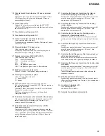
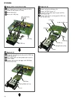
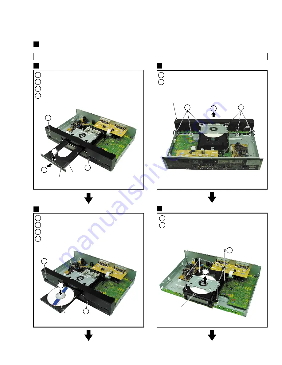
Remove the Bonnet (Screws
×
7)
2
Power ON
3
Tray open (
0
)
4
Remove the Tray Panel
1
Set the Test Disc
2
Tray close (
0
)
→
Clamp the Test Disc
1
Unhook (
×
6)
2
Remove the Front Panel
3
Power OFF
4
Pull out the Power Cord from the outlet
Bonnet and Tray Panel
1
Test Disc Set
2
Front Panel Assy
3
2
3
3
2
4
1
Tray
Test Disc
Tray Panel
3
1
×
3
1
×
3
7.1.7 DISASSEMBLY
Note
When diagnosing the unit, be sure to use two connection cables for service. (Part No. : GGD1271)
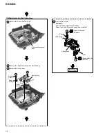
DIAGNOSIS OF PCBs
2
Front Panel Assy
Loading Mechanism Assy
4
Loading
Mechanism
Assy
1
×
4
1
Remove four screws.
2
Remove the Loading Mechanism Assy.
(Remove the Connector (
×
2).)
2
Summary of Contents for DV-646A
Page 9: ...DV 646A 9 ...
Page 15: ...DV 646A 15 ...
Page 38: ...DV 646A 38 ...
Page 46: ...A B C D 1 2 3 4 1 2 3 4 46 DV 646A D 4 4 SCRB ASSY CN702 C VNP1838 A SIDE A SCRB ASSY D ...
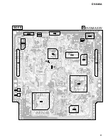
Page 65: ...65 DV 646A DVDM ASSY B SIDE B TE FE ...
Page 101: ...101 DV 646A 8 PANEL FACILITIES AND SPECIFICATIONS 8 1 PANEL FACILITIES 8 1 1 Front Panel ...
Page 102: ...102 DV 646A 8 1 2 Remote Control ...
Page 103: ...103 DV 646A 8 1 3 Display Window ...

