DVR-3100-S
114
1
2
4
1
2
4
C
D
F
A
B
E
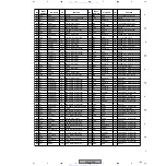
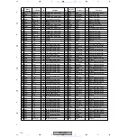
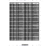
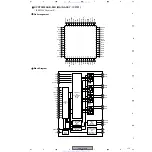
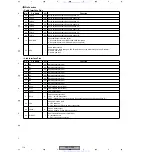
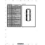
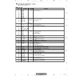
Pin Function
• Cable Interface Pins
• Link Interface Pins
No.
Pin Name
I/O
Function
39
TpA0p
I/O
Port 0 twisted pair cable A positive phase I/O
38
TpA0n
I/O
Port 0 twisted pair cable A negative phase I/O
37
TpB0p
I/O
Port 0 twisted pair cable B positive phase I/O
36
TpB0n
I/O
Port 0 twisted pair cable B negative phase I/O
46
TpA1p
I/O
Port 1 twisted pair cable A positive phase I/O
45
TpA1n
I/O
Port 1 twisted pair cable A negative phase I/O
44
TpB1p
I/O
Port 1 twisted pair cable B positive phase I/O
43
TpB1n
I/O
Port 1 twisted pair cable B negative phase I/O
19
SUS/RES
I
Suspend/Resume function select
1 : Suspend/Resume on (IEEE1394a-2000 compliant)
0 : Suspend/Resume off (P1394a draft 1.3 compliant)
32
CPS
I
Cable power status
Connect to the cable through a 390 k
Ω
resistor and to the GND through a 100 k
Ω
resistor.
0 : Cable power fail
1 : Cable power on
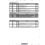
No.
Pin Name
I/O
Function
8
D0
I/O
Data input/output (bit 0)
9
D1
I/O
Data input/output (bit 1)
11
D2
I/O
Data input/output (bit 2)
12
D3
I/O
Data input/output (bit 3)
14
D4
I/O
Data input/output (bit 4)
15
D5
I/O
Data input/output (bit 5)
17
D6
I/O
Data input/output (bit 6)
18
D7
I/O
Data input/output (bit 7)
5
CTL0
I/O
Link interface control (bit 0)
6
CTL1
I/O
Link interface control (bit 1)
63
LREQ
I
Link request input
2
SCLK
O
Link control output clock
LPS 1 : 49.152 MHz output
LPS 0 : Clamp to 0 (The clock signal will be output within 25
µ
sec after change to "0")
Link power status input
0 : Link power off
1 : Link power on (PHY/Link direct connection)
Link-on signal output
Link-on signal is 6.1444 MHz clock output.
PHY/Link isolation barrier control input
0 : Isolation barrier
1 : PHY/Link direct connection
www. xiaoyu163. com
QQ 376315150
9
9
2
8
9
4
2
9
8
TEL 13942296513
9
9
2
8
9
4
2
9
8
0
5
1
5
1
3
6
7
3
Q
Q
TEL 13942296513 QQ 376315150 892498299
TEL 13942296513 QQ 376315150 892498299


