background image

 ADJUSTMENT

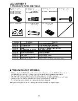
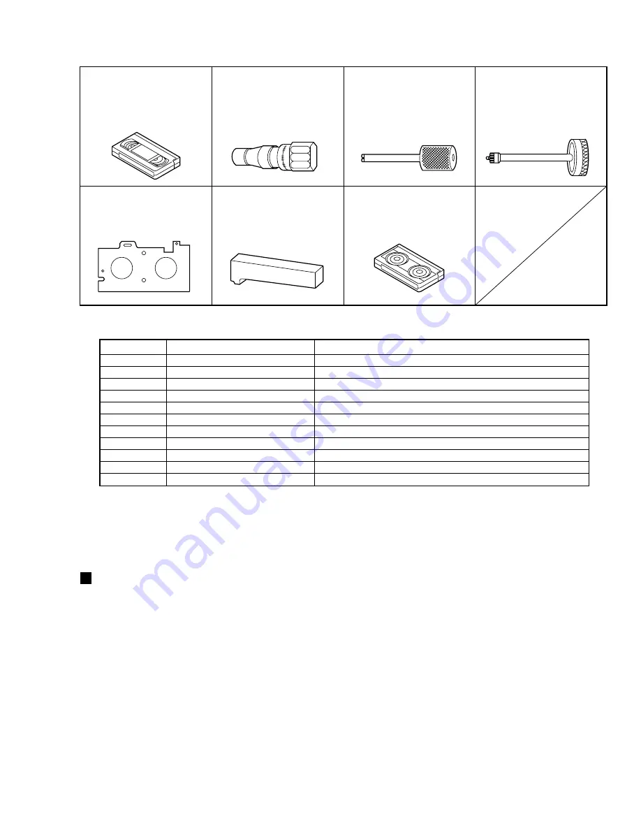
  SERVICING FIXTURES AND TOOLS

(For 4 heads model)

VHS Alignment Tape
GGV1183 (VN

1

S-LI6

3

H)

GGV1184 (VN

1

S-X6

3

)

GGV1185 (VN

2

E-LI6

3

H)

GGF1506 Adapter
GGF1507 Dial Torque Gauge

(10~90 gf•cm)

GGF1508 (60~600 gf•cm)

GGF1509 Post Adjustment

Screwdriver

Part No. SV-TG0-030-000 (small)

GGF1510 X Value Adjustment

Screwdriver

GGF1511 Master Plane

GGF1512 Reel Disk Height

Adjustment Jig

GGV1186 Torque Tape

(VHT-063)

Part No.

Parts Name

Remarks

GGV1183

VHS Alignment Tape

Hi-Fi Audio 

(For 4 heads model)

GGV1184

VHS Alignment Tape

X Value Adjustment 

(For 4 heads model)

GGV1185

VHS Alignment Tape

EP Monoscope, 6 kHz 

(For 4 heads model)

GGF1506

Adapter

VSR Torque, Brake Torque (S Reel/T Reel Assy)

GGF1507

Dial Torque Gauge (10~90 gf•cm)

Brake Torque (T Reel Assy)

GGF1508

Dial Torque Gauge (60~600 gf•cm)

VSR Torque, Brake Torque (S Reel)

GGF1509

Post Adjustment Screwdriver

Guide Roller Adjustment

GGF1510

X Value Adjustment Screwdriver

X Value Adjustment

GGF1511

Master Plane

Reel Disk Heifht Adjustment

GGF1512

Reel Disk Height Adjustment Jig

Reel Disk Heifht Adjustment

GGV1186

Torque Tape (VHT-063)

Playback Torque, Back Tension Torque During Playback

PREPARATION FOR SERVICING

1. While pressing the CH DOWN button on the set for more than 2 seconds, press the POWER button on the set 

simultaneously at the Power OFF. Although the DVD is connected, the DVD mode cannot be selected.

2. Press both CH UP button on the set and the REC button on the set for more than 2 seconds.

(The BOT, EOT, and the Reel Sensor do not work and the VCR deck can be operated without a cassette tape.)

3. In case of using a cassette tape, press the EJECT button to insert or eject a cassette tape.

Turn on the power and re-check the cable before checking the trouble points.

When you servicing with connection of DVD, perform the operations above step 2 to step 3.

24

Summary of Contents for DVR-RT300-S/UXTLCA

Page 1: ...Training Guide VCR DVD RECORDER COMBO DVR RT500 S UXTLCA DVR RT300 S UXTLCA Technical Training Department 1925 East Dominguez Street Long Beach CA 90810 ...

Page 2: ......

Page 3: ...rding 12 Hour Meter 28 VCR to DVD Copy 13 Preventive Service Intervals 29 DVD to VCR Copy 14 Mechanical Adjustments 30 33 Sensor Block 15 Electrical Adjustments 34 35 Unit Overall Block 16 Region Number EEPROM Setting 36 37 MPEG Block 17 DVD Firmware Re Writing 38 Y C Audio CCD Head Amp 18 Measuring The Error Rate 39 System Control 19 Power On Sequence 40 HI FI Block 20 DVD Tape Removal no power 4...

Page 4: ...LINEUP MAIN FEATURES VCR DVD RECORDER COMBO DVR RT500 S UXTLCA DVR RT300 S UXTLCA VCR DVD PLAYER COMBO DV PT100 S UXTLCA 4 ...

Page 5: ... DVR RT500 S UXTLCA Regular model DVR RT300 S UXTLCA Derivative model DV PT100 S KUXTL 5 ...

Page 6: ...CR 2way recording from VHS to DVD and DVD to VHS 4 Way Recording mode XP 1H SP 2H LP 4H EP 6H MP3 WMA JPEG playback 99mm Height VCR Plus PIONEER DVD R RW Drive 4 Head VCR GUI Language English French Spanish 9 NO DV terminal 9 NO VIDEO CD and SVCD playback Features 6 ...

Page 7: ...yer VCR VCR Playback mode SP LP SLP VCR Recording mode SP SLP MP3 WMA JPEG playback GUI Language English French Spanish 9 NO DV terminal 9 NO VIDEO CD and SVCD playback 9 NO VR mode 9 NO Copy Disc to Tape 9 NO Pioneer s Remote Code Features 7 ...

Page 8: ...Block Diagrams VCR DVD RECORDER COMBO DVR RT500 S UXTLCA DVR RT300 S UXTLCA ...

Page 9: ...VCR DVD VCR DVD VIDEO VIDEO SW SW FRONT_A_IN_L R FRONT_A_IN_L R IC101 IC101 YC AUDIO CCD YC AUDIO CCD HEAD AMP HEAD AMP TU_V_OUT TU_V_OUT TU_A_OUT TU_A_OUT SIF_OUT SIF_OUT ST_A_OUT_L R ST_A_OUT_L R COMPOSITE_IN COMPOSITE_IN SPDIF SPDIF IC4001 IC4001 VADDIS V VADDIS V DVD CPU DVD CPU ATA I F ATA I F MPEG MPEG DECODER DECODER OSD OSD SPDIF SPDIF IC7301 IC7301 AUDIO AUDIO ADC ADC DAC DAC ADC ADAT ADC...

Page 10: ... DVD VIDEO VIDEO SW SW FRONT_A_IN_L R FRONT_A_IN_L R IC101 IC101 YC AUDIO CCD YC AUDIO CCD HEAD AMP HEAD AMP TU_V_OUT TU_V_OUT TU_A_OUT TU_A_OUT SIF_OUT SIF_OUT ST_A_OUT_L R ST_A_OUT_L R COMPOSITE_IN COMPOSITE_IN SPDIF SPDIF IC4001 IC4001 VADDIS V VADDIS V DVD CPU DVD CPU ATA I F ATA I F MPEG MPEG DECODER DECODER OSD OSD SPDIF SPDIF IC7301 IC7301 AUDIO AUDIO ADC ADC DAC DAC ADC ADAT ADC ADAT TU_AU...

Page 11: ...DVD VCR DVD VIDEO VIDEO SW SW FRONT_A_IN_L R FRONT_A_IN_L R IC101 IC101 YC AUDIO CCD YC AUDIO CCD HEAD AMP HEAD AMP TU_V_OUT TU_V_OUT TU_A_OUT TU_A_OUT SIF_OUT SIF_OUT ST_A_OUT_L R ST_A_OUT_L R COMPOSITE_IN COMPOSITE_IN SPDIF SPDIF IC4001 IC4001 VADDIS V VADDIS V DVD CPU DVD CPU ATA I F ATA I F MPEG MPEG DECODER DECODER OSD OSD SPDIF SPDIF IC7301 IC7301 AUDIO AUDIO ADC ADC DAC DAC ADC ADAT ADC ADA...

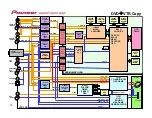
Page 12: ... R IC101 IC101 YC AUDIO CCD YC AUDIO CCD HEAD AMP HEAD AMP TU_V_OUT TU_V_OUT TU_A_OUT TU_A_OUT SIF_OUT SIF_OUT COMPOSITE_IN COMPOSITE_IN SPDIF SPDIF IC4001 IC4001 VADDIS V VADDIS V DVD CPU DVD CPU ATA I F ATA I F MPEG MPEG DECODER DECODER OSD OSD SPDIF SPDIF ADC ADAT ADC ADAT TU_AUDIO_L R TU_AUDIO_L R BS_AUDIO L R BS_AUDIO L R AUDIO_IN_1 AUDIO_IN_1 AUDIO_IN_2 AUDIO_IN_2 DAC_L R DAC_L R AOUT0 AOUT0...

Page 13: ...A_IN_L R IC101 IC101 YC AUDIO CCD YC AUDIO CCD HEAD AMP HEAD AMP TU_V_OUT TU_V_OUT TU_A_OUT TU_A_OUT SIF_OUT SIF_OUT ST_A_OUT_L R ST_A_OUT_L R COMPOSITE_IN COMPOSITE_IN SPDIF SPDIF IC4001 IC4001 VADDIS V VADDIS V DVD CPU DVD CPU ATA I F ATA I F MPEG MPEG DECODER DECODER OSD OSD SPDIF SPDIF ADC ADAT ADC ADAT TU_AUDIO_L R TU_AUDIO_L R BS_AUDIO L R BS_AUDIO L R AUDIO_IN_1 AUDIO_IN_1 AUDIO_IN_2 AUDIO_...

Page 14: ...IDEO SW SW FRONT_A_IN_L R FRONT_A_IN_L R IC101 IC101 YC AUDIO CCD YC AUDIO CCD HEAD AMP HEAD AMP TU_V_OUT TU_V_OUT TU_A_OUT TU_A_OUT SIF_OUT SIF_OUT ST_A_OUT_L R ST_A_OUT_L R COMPOSITE_IN COMPOSITE_IN SPDIF SPDIF IC4001 IC4001 VADDIS V VADDIS V DVD CPU DVD CPU ATA I F ATA I F MPEG MPEG DECODER DECODER OSD OSD SPDIF SPDIF IC7301 IC7301 AUDIO AUDIO ADC ADC DAC DAC ADC ADAT ADC ADAT TU_AUDIO_L R TU_A...

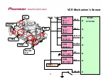
Page 15: ...Q3001 REEL REEL S S SENS SENS Q3008 Q3008 BOT SENS BOT SENS Q3006 Q3006 EOT SENS EOT SENS 69 69 REEL REEL S S REEL REEL T T MS SEN MS SEN B B MS SEN MS SEN A A EOT EOT BOT BOT 70 70 27 27 28 28 26 26 25 25 AT 5 2V AT 5 2V P CON 5V P CON 5V S REEL S REEL T REEL T REEL MS SEN MS SEN A B A B EOT EOT BOT BOT TAB SW TAB SW 51 51 TAB_SW TAB_SW D3001 D3001 15 ...

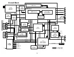
Page 16: ...dis V MPEG Decoder w CPU MPEG Block Power Supply CV S L R S OP V CO L R CV L R U Y REAR CV S L R FRONT SW_C_VIDEO REAR CVBS FRONT CVBS REAR L R FRONT L R REAR CVBS FRONT CVBS SP SLP CH1 2 SP SLP CH1 2 NORMAL A TU VCR_V FRONT L R REAR L R CVBS CVBS DVD AUDIO L R AUDIO OUT L R TUNER_VIDEO SIF Y C_VIDEO Y C_VIDEO RF AUDIO OUT CVBS OUT AUDIO OUT L R 32 768kHz 10MHz 14 31818MHz 3 579545MHz ATAPI FFC HE...

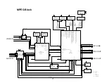
Page 17: ...DQM MWE MCLK MA0 12 MD16 31 HY57V561620CT 7 256MBIT SDRAM IC4007 MD0 15 CVBSIN ZR36750E SBVALID SBDAT SBCLK SBREQ VIDHS VIDVS VIDCLK VIDVLD VID0_7 DATA LINE MPEG_DATA_IN MPEG_DATA_OUT VADDIS_INT MPEG_CS MPEG_CLK AMCLK_SEL MPEG 27M_OSC I55_TX0 I55_RX0 MPEG ENCODER 27M_OSC I55_AODAT I55_AODAT I55_AMCLK I55_ALRCLK I55_ABCLK I55_ALRCLK I55_ABCLK ADC_ADAT ADC_ADAT ADC_ADAT 12 5 11 1 48 13 10 7 4 6 19 1...

Page 18: ...H AMP_SW C ROTARY H SW ENV DET COMP DUMMY_V SYNC C SYNC F R_V_IN TU_V_OUT NORMAL_A_IN NORMAL_A_OUT 6 2 3 1 5 Q105 BIAS CTL 11 4 P CON 5V H AMP SW AUDIO MUTE C ROT RF SW IN ENV DET CONP OUT Q104 BIAS OSC Q103 SW Q101 Q102 AUDIO PB SW HF1 HF2 HI FI DEMODU LATOR HF_COM COIL BIAS OSC X101 3 578545M Hz VX01 50 49 PULL 41 Q109 BUFFER TUNER JACK SYSCON HI FI DEMODU LATOR 80 SERIAL DECODER AUDIO_MUTE H V ...

Page 19: ...REO SE L 31 ST SELECT 64 MP DATA OUT 25 C ROTARY 99 C ROTARY 5 LDM CTL CP3001 OPERATION DISPLAY VADDIS_RESET VADDIS INT 44 83 REAR S SW KEY A 30 45 KEY B 29 MPEG_RESET VADDIS INT REAR S SW KEY A KEY B FL_CLK REM IN 43 48 FL_CLK REM_IN FL_DATA 49 FL_DATA FL_CS 47 FL_CS CYL _CTL 2 3 4 1 2 3 4 1 REEL SENS Q3002 REEL SENS Q3001 REEL T 70 REEL S 69 2 3 4 1 P CON 5V 59 60 MPEG_DATA 42 MPEG_CLK HiFi DEMO...

Page 20: ...M LIM DEM BLOCK AMP AMP AGC LOGIC VCO FO ADJ LOGIC DBX NOISE REDUCTION L R MIX REC LPF VCO 14 9 FRONT_A_IN_L FRONT_A_IN_R OPERATION DISPLAY DVD_A_OUT_L AV SW DVD_A_OUT_R 3 2 REAL_A_IN_L REAL_A_IN_R 19 18 14 TU_A_OUT STEREO IC IC801 AN5829S 22 21 ST_A_OUT_L ST_A_OUT_R TUNER JACK HIFI_A_OUT_L HIFI_A_OUT_R AV SW 25 P CON 5V 58 P CON 12V 51 P CON 5V 7 P CON 5V REGULATOR 59 ALC_A_OUT TUNER JACK 56 ST_S...

Page 21: ...DVD_A_OUT R DVD_A_OUT L SPDIF AV SW V PR _V_OUT U PB _V_OUT Y G _V_OUT Q8009 ASP CTL Q8010 ASP CTL Q8008 ASP CTL DVD_Y_V_OUT DVD_C_V_OUT ASP1 ASP2 HiFi_A_OUT L HiFi_A_OUT R MUTE L ZERO MUTE L REAR_C_IN REAR_Y_IN REAR_A_IN_L REAR_A_IN_R REAR_A_IN_L REAR_A_IN_R ALC_A_OUT TU_A_OUT SIF_OUT REAR_V_IN FSC TU_V_OUT VCR H P_MUTE L AFT S CURVE SCL SDA REAR_S_SW V_OUT TV VCR RF_SW TU_A_MUTE H MUTE SW Q302 A...

Page 22: ...RONT REAR Y SW IC8302 NJM2534V 7 8 1 3 5 AMP IC8301 NJM4580M TE1 P CON 12V REFULATOR ST_A_OUT_L HiFi_A_OUT_L REAR_A_IN_R REAR_A_IN_L ST_A_OUT_R HiFi_A_OUT_R FRONT_A_IN_L FRONT_A_IN_R REAR_Y_IN REAR_C_IN FRONT_Y_IN FRONT_C_IN MUTE L ASP2 ASP1 ZERO_MUTE L SPDIF VADDIS INT MPEG DATA MPEG CLK MP_DATA OUT MP_DATA IN MP_CLK MPEG_RESET VCR_DUB H VCR_V_OUT1 TU_V_OUT V PR _V_OUT U PB _V_OUT Y G _V_OUT DVD_...

Page 23: ...TER 22V TUNER 32V P FAIL DRIVE ON H UNREG 3 3V UNREG 3 3V AT 5 2V AT 5 2V AT 13V MOTOR 12V CP502 REGULATOR 4 1 P CON D5V P CON 12V CP504 DVD LOADER UNIT 18 IC502 DRIVE 12V REG KIA278R12PI 1 2 IC501 KIA431A AT VOLTAGE CTL IC 3 1 3 4 1 2 12 13 16 1 P CON 12V CP506 15 Q505 DRIVE 5V SW FAD MOTOR Q503 SAFTY SW 4 Q504 SAFTY SW 23 Power Supply Block ...

Page 24: ...S Reel GGF1509 Post Adjustment Screwdriver Guide Roller Adjustment GGF1510 X Value Adjustment Screwdriver X Value Adjustment GGF1511 Master Plane Reel Disk Heifht Adjustment GGF1512 Reel Disk Height Adjustment Jig Reel Disk Heifht Adjustment GGV1186 Torque Tape VHT 063 Playback Torque Back Tension Torque During Playback PREPARATION FOR SERVICING 1 While pressing the CH DOWN button on the set for m...

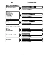
Page 25: ...K 4 1 4 CONFIRMATION OF VSR TORQUE 5 1 5 CONFIRMATION OF REEL BRAKE 1 CONFIRMATION AND ADJUSTMENT 6 2 1 GUIDE ROLLER 7 2 2 CONFIRMATION AND ADJUSTMENT OF AUDIO CONTROL HEAD 8 2 3 TAPE RUNNING ADJUSTMENT X VALUE ADJUSTMENT 9 2 4 CONFIRM HI FI AUDIO 2 CONFIRMATION AND ADJUSTMENT OF TAPE RUNNING MECHANISM 10 Electrical Part 1 1 PG SHIFTER 11 DVD SIDE EEPROM IC4002 INITIAL SETTING REPLACING EEPROM IC4...

Page 26: ...ASSY VCR MT PCB ASSY 10 None Mechanical point Electrical point Replacing HEAD AUDIO CONTROL CYLINDER UNIT ASSY 6 10 7 8 9 Mechanical point Electrical point Replacing IC4002 DVD SIDE EEPROM None 11 Mechanical point Electrical point Replacing DVD LOADER None 12 Mechanical point Electrical point Replacing TENSION BAND TENSION CONNECT TENSION ARM ASSY T BRAKE BAND T BRAKE SPRING T BRAKE ARM IDLLER ASS...

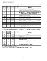
Page 27: ... CH CH 2 For setting tracking to the center value Note You can enter this mode by holding the ATR key on the remote control unit pressed for 2 seconds VCR Playback REC OTR DVD VCR 2 For automatic adjustment of the PG shifter VCR CH REC OTR 2 For entering Service mode Entering this mode disables the EOT BOT reel sensor and enables the VCR section of the unit to operate even if a tape is not loaded ...

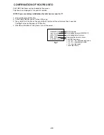
Page 28: ... and set to the VCR mode 3 Press both CH UP button on the set and the FF button on the set for more than 2 seconds The Fig 1 screen will appear on TV Monitor 4 After the confirmation of using hours turn off the power Fig 1 MICON Version Initial setting content of MEMORY IC Initial setting data check sum Romcorrection data check sum PLAY REC total hours 16 16 16 thousands digit value 16 16 hundreds...

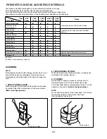
Page 29: ...lace when rolling becomes abnormal Cylinder Unit 7 Clean the Head 7 Clean Check it and if necessary replace it NOTE After cleaning the heads with isopropyl alcohol do not run a tape until the heads dry completely If the heads are not completely dry and alcohol gets on the tape damage may occur 1 AUDIO CONTROL HEAD Clean the Audio Control Head with the cotton stick soaked by alcohol Clean the full ...

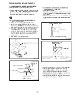
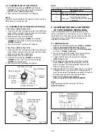
Page 30: ...just the adjusting section for the Tension Arm position so that the Tension Arm top is within the standard line of Main Chassis 3 While turning the S Reel clockwise confirm that the edge of the Tension Arm is located in the position described above USING A CASSETTE TYPE TORQUE TAPE JG100A 1 After confirmation and adjustment of Tension Post position Refer to item 1 2 load the cassette type torque t...

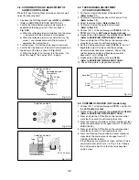
Page 31: ...ning mechanism because of long term usage or failure the confirmation and adjustment are necessary 2 1 GUIDE ROLLER 1 Playback the VHS Alignment Tape JG001 or JG001B Refer to SERVICING FIXTURE AND TOOLS 2 Connect CH 1 of the oscilloscope to TP101 Envelope and CH 2 to TP3002 SW Pulse 3 Press and hold the ATR button on the remote control more than 2 seconds to set tracking to center 4 Trigger with S...

Page 32: ...FIXTURE AND TOOLS 7 Press and hold the ATR button on the remote control more than 2 seconds to set tracking to center 8 Set the X Value adjustment driver JG153 to the 4 of Fig 2 2 B Adjust X value so that the envelope waveform output becomes maximum Check if the relation between Audio and Envelope waveform becomes 1 or 2 of Fig 2 3 9 Playback the VHS Alignment Tape JG195 Refer to SERVICING FIXTURE...

Page 33: ...ATION GUIDE 9 10 8 7 6 5 4 3 2 1 1 Tension Connect 2 Tension Arm 3 Guide Roller 4 Audio Control Head 5 X value adjustment driver hole 6 P4 Post 7 T Brake Spring 8 T Reel 9 S Reel 10 Adjusting section for the Tension Arm position 33 ...

Page 34: ... all the old silicon grease Old grease may cause damages to the IC and Transistor 1 1 PG SHIFTER CONDITIONS MODE PLAYBACK Input Signal Alignment Tape JG001B INSTRUCTIONS 1 Connect CH 1 on the oscilloscope to TP3002 and CH 2 to J8005 2 Playback the alignment tape JG001B 3 Press and hold the Tracking Auto button on the remote control more than 2 seconds to set tracking to center 4 Press both CH UP b...

Page 35: ...4 CP8302 CP8301 CP1701 CP1703 J8002 J8005 J8006 J8003 J8001 J654 CP651 TP8301 TP8302 CP681 DVD HD MPEG PCB POWER PCB OPERATION PCB DECK CD CP103 FE HEAD CP102 AC HEAD CD102 CD651 CP506 CP502 CP504 CP7301 CP7302 CP7303 CP7304 CD7304 VCR PCB FAN MOTOR CD502 CD7301 CD7302 CD7303 CP4001 OS651 CP501 CD501 AC IN B C A D CD4001 CD504 35 ...

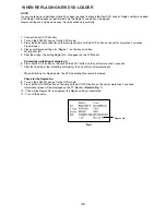
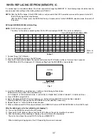
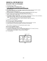
Page 36: ...ray and close Writing will start 5 After the writing the writing Region No will appear on the TV Monitor Perform the initializing of shipping 6 Press both CH UP button on the set and the PLAY button on the set for more than 2 seconds 7 After the finishing of the initializing of shipping the unit will turn off automatically When initializing to shipping data the VCR operating time record is cleared...

Page 37: ...OSE C DVD VCR D TIMER REC E INPUT SELECT F DISPLAY CALL 5 Press ENTER to select DATA 6 Again step through the DATA using Channel or button until required DATA value has been selected 7 Pressing ENTER will take you back to ADDRESS for further selection if necessary 8 Repeat steps 4 to 7 until all data has been checked 9 When satisfied correct DATA has been entered turn POWER off return to STANDBY M...

Page 38: ... indication will disappear and the tray will close automatically When the Please Reboot appears on the screen the writing will be finished NOTE Do not turn off the unit on the way or push the tray by hand to close it Up Date error will happen and can not be done with the Up Date of Up Date Disc 11 Unplug the AC cord then plug it in After the write set to the initializing of shipping 12 Turn on the...

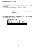
Page 39: ...ted 4 To clear the error rate display from the screen press 9 on the remote control and STOP on the main unit at the same time again When clearing this display the error rate measurement is not executed Fig 1 Background is input picture State xxh numerator of PO xxx denominator of PO xxx numerator of PI xxx denominator of PI xxx Error rate value numerator of PI denominator of PI decimal digit Tabl...

Page 40: ...717 P ON SW BLOCK P CON 12V IC701 HI FI IC REGULATOR SIDE HEATER FIP 22V IC651 FIP DRIVER AT 13V IC1701 VOLT CURRENT CONTROL UNREG 3 3V MP_P CON1 8V 3 3V REGULATOR MPEG_P_ON L Q1701 MP POWER SW MP_P CON 1 8V DVD BLOCK MP_P CON 3 3V DVD BLOCK DVD MPEG5V_ON H from U COM from U COM Q1722 MPEG P CON SW BLOCK MP_P CON 5V DVD BLOCK DRIVE_ON H from U COM IC502 DRIVE 12V REGULATOR P CON 12V DVD UNIT FAN M...

Page 41: ... the Loading Motor from the insert hole for screw driver and remove the Loading Motor 3 Rotate the Pinch Roller Cam in the direction of the arrow by hand to slacken the Video Tape Refer to Fig 2 4 Rotate the Clutch Ass y either of the derections to wind the Video Tape in the Cassette Case 5 Repeat the above step 3 4 Then take out the Video Cassette from the Deck Chassis Be careful not to scratch o...

Page 42: ... The 4 digit password has now been cleared NB No indications on the screen when the Parental Lock is setting 4 DIGIT PASSWORD CANCELLATION Tray cannot be opened by setting the Tray Lock please follow the steps below 1 Turn Unit ON 2 Press and hold the 0 key on the remote control unit 3 Simultaneously press and hold the STOP key on the front panel 4 Hold both keys for more than 2 seconds 5 Press th...

Page 43: ...ection of arrow B 6 Remove the 4 screws 3 7 Remove the MPEG Shield in the direction of arrow C 8 Disconnect the following connector CP4001 9 Remove the DVD HD MPEG PCB in the direction of arrow D 10 Remove the 2 screws 4 11 Remove the DVD Angle L in the direction of arrow E 12 Remove the 2 screws 5 13 Remove the DVD Angle R in the direction of arrow F 1 2 FLAP Refer to Fig 1 2 1 Open Flap to 90 an...

Page 44: ...ion of arrow 1 5 VCR DECK Refer to Fig 1 5 NOTE Do not remove the cable at the FE Head section The FE Head may be damaged if you remove the cable by force 1 Unlock the 2 supports 1 and remove the Top Holder 2 Remove the screw 2 3 Remove the FE Head 4 Move the Cassette Holder Assy to the back side 5 Remove the 3 screws 3 6 Disconnect the following connectors CP101 CP102 CP3001 7 Remove the AC Head ...

Page 45: ...ject position 2 Unlock the support 1 3 Remove the A side of the Link Unit first then remove the B side 2 5 LINK LEVER FLAP LEVER Refer to Fig 2 5 1 Extend the support 1 2 Remove the Link Lever 3 Remove the Flap Lever Fig 2 1 Fig 2 3 B Fig 2 4 Fig 2 5 1 1 1 1 1 1 2 1 2 2 1 Top Bracket Top Bracket Main Chassis Main Chassis Main Chassis Locker Spring Locker R Locker R Cassette Side R Check it this po...

Page 46: ...m Assy 5 Unlock the support 3 and remove the Tension Connect 6 Float the hook 4 and turn it clockwise then remove the Tension Holder NOTE 1 In case of the Tension Band installation note the direction of the installation Refer to Fig 2 7 C 2 In case of the Tension Band installation install correctly as Fig 2 7 D 3 In case of the Tension Connect installation install as the circled section of Fig 2 7...

Page 47: ... T Reel Use gloves Refer to Fig 2 9 A Do not adhere the stains on it 5 When you install the reel clean the shaft and grease it FG 84M If you do not grease noise may be heard in FF REW mode 6 After installing the reel adjust the height of the reel Refer to MECHANICAL ADJUSTMENT NOTE 1 In case of the S Reel and T Reel installation check if the correct parts are installed Refer to Fig 2 9 B 2 In case...

Page 48: ...RECORDER ONLY Refer to Fig 2 12 1 Remove the screw 1 2 Remove the FE Head 2 13 AHC ASSY CYLINDER UNIT ASSY Refer to Fig 2 13 1 Unlock the support 1 and remove the AHC Assy 2 Disconnect the following connector CD2001 3 Remove the 3 screws 2 4 Remove the Cylinder Unit Assy NOTE 1 When you install the Cylinder Unit Assy tighten the screws from 1 to 3 in order while pulling the Assy toward the left fr...

Page 49: ...e met Refer to Fig 2 15 B 2 16 LOADING GEAR S T UNIT Refer to Fig 2 16 A 1 Remove the E Ring 1 and remove the Main Loading Gear 2 Remove the Main Rod Tension Lever Loading Arm S Unit and Loading Arm T Unit NOTE 1 When you install the Loading Arm S Unit Loading Arm T Unit and Main Loading Gear align each marker Refer to Fig 2 16 B Fig 2 14 Fig 2 15 A Fig 2 15 B Fig 2 16 B 1 1 1 2 2 2 2 Capstan Belt...

Page 50: ...ecording the disc recorded with this unit can be played back with other DVD players Recording editing or playback of an unfinalized disc can be done only with this unit However there is some limitation to editing operations In this mode you cannot record a Copy Once program When you record a TV program of a bilingual broadcast only one of the audio modes can be recorded You have to select it Forma...

Page 51: ...C L 150MM CORD JUMPER 2H0I1802 18PIN L 180MM P 1 0MM 06CU2A2701 CD7304 06CU252802 CD651 06CU641202 CD504 12BH040061 CD4001 122F061501 CD102 122H0I1802 CD7303 122H0K1802 CD7301 122H0K1802 CD7302 REF NO Used part Parts Code CORD JUMPER 2H0K1802 20PIN L 180MM P 1 0MM FFC CORD JUMPER 2H0K1802 20PIN L 180MM P 1 0MM FFC 2 When reattaching the POWER PCB Assy to the Plate bottom tighten the two screws for...

Page 52: ... signals 8 Be sure to reattach the Shield 3 Pin to the front jack and the Shield Compo to the rear jack of the VCR MT PCB Assy Those are for preventing electrostatics 9 Be sure to reattach the Shield 3 Pin so that part of it protrudes from the Plate bottom Be careful that the Shield 3 Pin is not embedded between the Plate bottom and the circuit board 52 ...

Page 53: ... L L Left LED Light Emitting Diode LIMIT AMP Limiter Amplifier LM LDM Loading Motor L LP Long Play L P F Low Pass Filter LUMI Luminance M M Motor MAX Maximum MINI Minimum MIX Mixer mixing MM Monostable Multivibrator MOD Modulator Modulation MPX Multiplexer Multiplex MS SW Mecha State Switch N NC Non Connection NR Noise Reduction O OSC Oscillator OPE Operation P PB Playback PB CTL Playback Control ...

Page 54: ...orque Brake Torque S Reel T Reel Assy Brake Torque T Reel Assy Dial Torque Gauge 60 600 gf cm GGF1508 VSR Torque Brake Torque S Reel Post Adjustment Screwdriver GGF1509 X Value Adjustment Screwdriver GGF1510 Guide Roller Adjustment X Value Adjustment Mater Plane GGF1511 Reel Disk Height Adjustment Reel Disk Height Adjustment Jig GGF1512 Torque Tape VHT 063 GGV1186 Reel Disk Height Adjustment Playb...

Page 55: ...jack STOP button DVD indicator VCR indicator CHANNEL buttons Display window Rear panel AC power cord FAN Make sure that when installed the fan is not obstructed DVD COAXIAL DIGITAL AUDIO OUT jack DVD VCR common AUDIO L R VIDEO OUTjacks DVD AUDIO L R OUT jacks DVD VCR common AUDIO L R VIDEO IN LINE 1 jacks DVD S VIDEO IN LINE 1 jack DVD S VIDEO OUT jack DVD COMPONENT OUT jacks DVD OPTICAL DIGITAL A...

Page 56: ......

Reviews: