DVR-RT500-S
106
1
2
3
4
1
2
3
4
C
D
F
A
B
E
7.9 CAUTIONS ON DIASSEMBLING AND ASSEMBLING
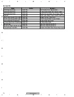
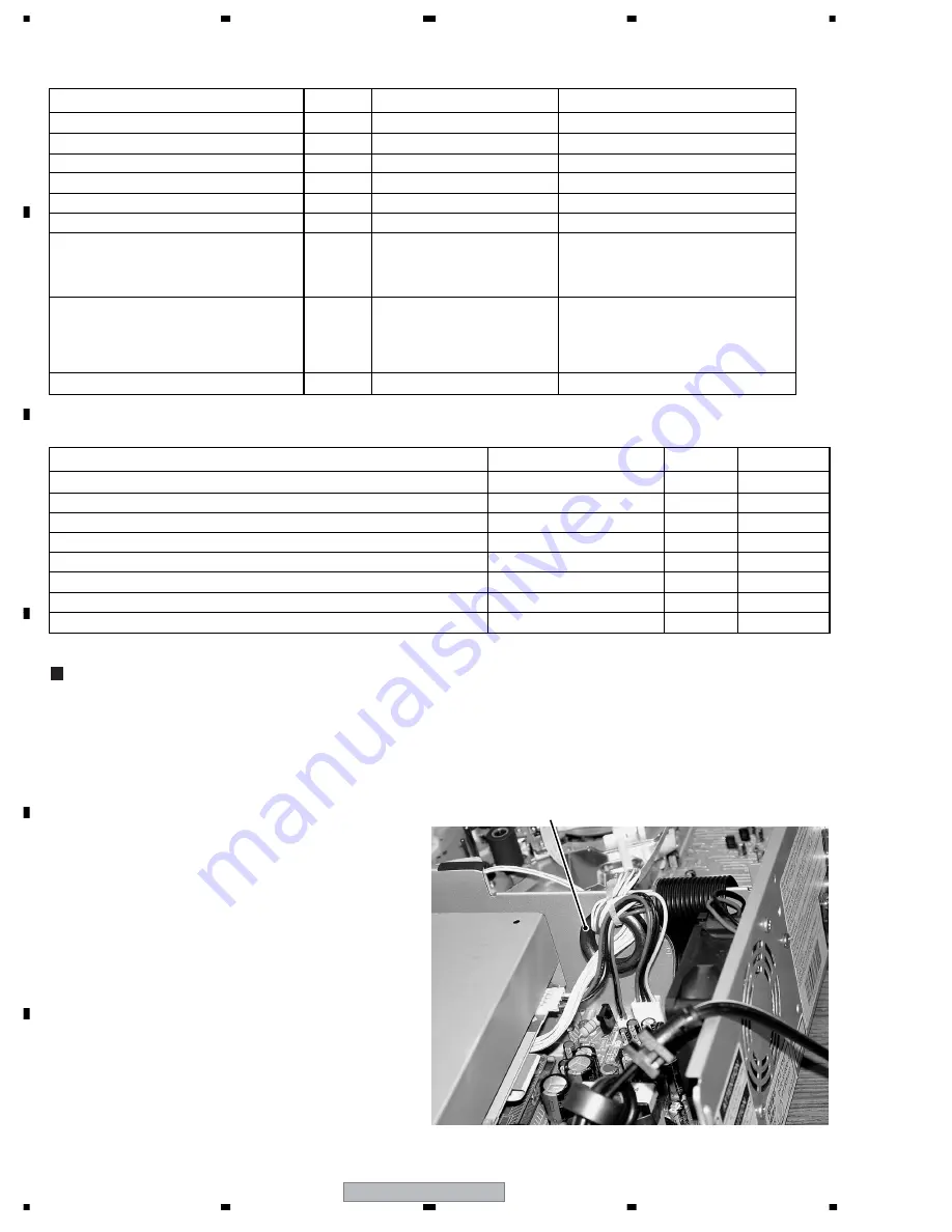
Screw List
Parts Name
SCREW, TAP TITE(B) WH7 3*10 CH
1
HEAT SINK
8109I30A0U
Num.
Used part
Parts Code
SCREW, TAP TITE(P) WH10 M2.6*8 CH
1
SPRING of DVD FLAP
8110E2680U
SCREW, TAP TITE(P) BIND 2.6*8 CH
3
OPERATION PCB
8110022680U
SCREW, BIND 3*6 CH
4
ANGLE DVD + LOADER
810223060U
SCREW, TAP TITE(S) BIND 3*4 CH
1
TUNER
810723040U
SCREW, TAP TITE(B)R PAN 3*29 CH
3
VCR DECK
8109130B9U
SCREW, TAP TITE(B) BIND(3D) 3*6 NI
5
CABINET TOP
8109K30601
SCREW, TAP TITE(B) R BIND 3*7 CH
13
1
4
6
2
VCR PCB
MPEG PCB
ANGLE DVD + BOTTOM
ANGLE DVD + SHIELD
810923070U
SCREW, TAP TITE(B) BIND 3*8 CH
12
3
4
2
2
POWER PCB
3PIN JACK
FAN
S-VIDEO
1
OPTICAL JACK
810923080U
CORD CONNECTOR, CORD JUMPER List
CAUTION
Ferrite Core
Parts Name
CORD CONNECTOR
CU2A2701
VCR
⇔
MPEG 10 wires
VCR
⇔
OPERATION
DVD DECK
⇔
MPEG
VCR
⇔
AC HEAD
MPEG
⇔
VCR
MPEG
⇔
VCR
MPEG
⇔
VCR
DVD DECK
⇔
POWER for DECK Power
L=270MM P=2.0MM 10PIN
CORD CONNECTOR
CU2252802
L=285MM P=2.0MM 5PIN
CORD CONNECTOR
CU641202
4PIN L=120MM P=2.5MM
CORD JUMPER
BH040061
L=60MM P=0.5MM H=8MM 40PIN
CORD JUMPER
2F061501
6PIN FFC L=150MM
CORD JUMPER
2H0I1802
18PIN L=180MM P=1.0MM
06CU2A2701
CD7304
06CU252802
CD651
06CU641202
CD504
12BH040061
CD4001
122F061501
CD102
122H0I1802
CD7303
122H0K1802
CD7301
122H0K1802
CD7302
REF NO.
Used part
Parts Code
CORD JUMPER
2H0K1802
20PIN L=180MM P=1.0MM FFC
CORD JUMPER
2H0K1802
20PIN L=180MM P=1.0MM FFC
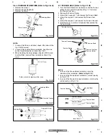
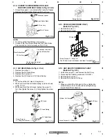
2. When reattaching the POWER PCB Assy to the Plate bottom, tighten the two screws for the round holes first then
tighten the screws for the slotted holes.
1. When reattaching the Front Cabinet, attach the cabinet pressing the Flap of VCR side toward inside.
3. When reattaching the Angle DVD to the DVD deck, tighten the screws for the round holes situated on the rear side first.
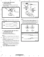
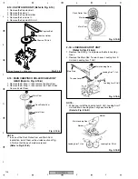
4. Insert each flexible cable straight, to avoid loose connection.
5. Be sure to pass the binder through the ferrite core that is
attached to the CD7304 (10 wires that connect between
MPEG and VCR) and secure and fix both the ferrite core
and the CD7304 using the binder. If only the wires are
secured but the ferrite core is not, the ferrite core may
have movement and become damaged.
6. When attaching the ferrite core to the CD7304, pass the
wires through it twice (one wind around it). Incorrect
attachment of the ferrite core may compromise its effects
of reducing spurious radiation.


